Ultrasonic wave analyzing device, ultrasonic wave analyzing method, and ultrasonic wave analyzing program

An analysis device, ultrasonic technology, applied in the direction of echo tomography, etc., can solve the problem of inability to accurately analyze the state of cartilage

Active Publication Date: 2018-09-28
FURUNO ELECTRIC CO LTD
View PDF14 Cites 0 Cited by
  • Summary
  • Abstract
  • Description
  • Claims
  • Application Information

AI Technical Summary

Problems solved by technology

[0007] In the ultrasonic analysis device of Patent Document 1, there is the following problem: Since the echo signal from the inside of the knee varies depending on the contact angle of the ult

Method used


Image

  • Ultrasonic wave analyzing device, ultrasonic wave analyzing method, and ultrasonic wave analyzing program
  • Ultrasonic wave analyzing device, ultrasonic wave analyzing method, and ultrasonic wave analyzing program
  • Ultrasonic wave analyzing device, ultrasonic wave analyzing method, and ultrasonic wave analyzing program

Examples


Embodiment Construction

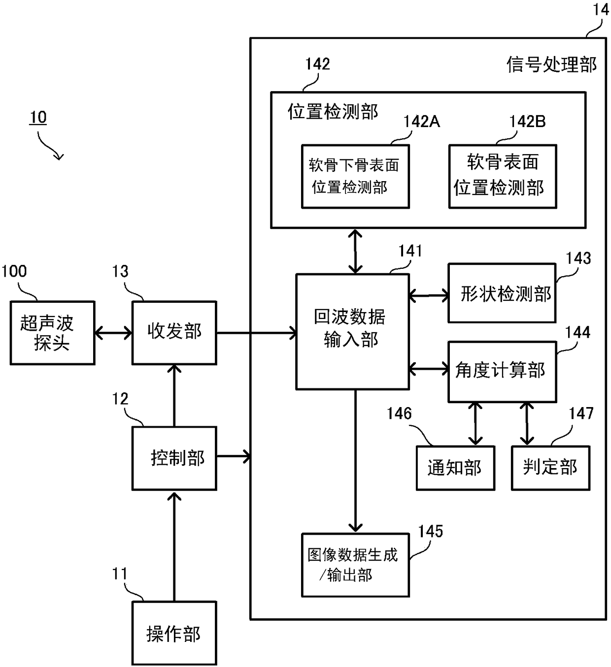
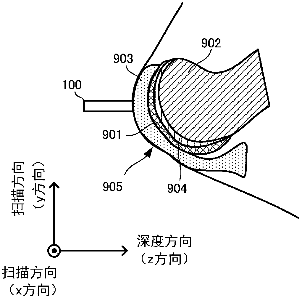
[0029] figure 1 It is a block diagram showing the configuration of the ultrasonic analysis device 10 according to the present embodiment. figure 2 It is a diagram showing the ultrasonic probe 100 and the subject of the ultrasonic analysis apparatus 10 according to the present embodiment. In this embodiment, an ultrasonic analysis device 10 , an ultrasonic analysis method, and an ultrasonic analysis program for analyzing the inside of a human knee as an example of a subject will be described.

[0030] The ultrasonic analysis device 10 includes an ultrasonic probe 100 . The ultrasonic probe 100 has two-dimensional ( figure 2 One vibrator (ultrasonic wave source) that scans mechanically in the x-direction and y-direction shown in . The vibrator transmits ultrasonic signals from the surface of the subject to the inside of the subject at predetermined time intervals. The transmitted ultrasonic signal is reflected inside the subject, and the vibrator receives the reflected ech...


PUM


Abstract

To provide an ultrasonic wave analyzing device, an ultrasonic wave analyzing method, and an ultrasonic wave analyzing program that can easily adjust the angle of contact of an ultrasonic probe to a subject. An ultrasonic wave analyzing device 10 comprising: a control unit 12 that controls an ultrasonic wave source so as to cause an ultrasonic signal to be transmitted from the ultrasonic wave source on a prescribed sound axis toward a plurality of mutually different positions on the surfaces of cartilage or the surfaces of subchondral bone of a subject; an echo data input unit 141 that receivesthe input of echo data of an echo signal formed by the ultrasonic signal transmitted by the control unit being reflected inside the subject; a position detection unit 142 that detects the position ofthe ultrasonic wave source and the positions of the mutually different plurality of cartilage surfaces or subchondral bone surfaces; a shape detection unit 143 that detects the shape of the cartilagesurface or the subchondral bone surface on the basis of information from each position detected by the position detection unit; and an angle calculation unit 144 that calculates the angle formed by the sound axis of the ultrasonic signal and the normal direction of the cartilage surface or the subchondral bone surface at the position where the ultrasonic signal is transmitted.

Description

technical field [0001] The present invention relates to an ultrasonic analysis device, an ultrasonic analysis method, and an ultrasonic analysis program for transmitting an ultrasonic signal into a subject and analyzing an echo signal of the ultrasonic signal reflected in the subject. Background technique [0002] As an apparatus for analyzing the state of cartilage, there is an ultrasonic analysis apparatus described in Patent Document 1, for example. The ultrasonic analysis device in Patent Document 1 transmits an ultrasonic signal from an ultrasonic probe in contact with the surface of the knee, and receives an echo signal reflected inside the knee by the ultrasonic probe. Then, the state of the cartilage is analyzed from the received echo signal. [0003] current technology [0004] patent documents [0005] Patent Document 1: Japanese Patent Laid-Open No. 2010-305 Contents of the invention [0006] The problem to be solved by the invention [0007] In the ultraso...

Claims


Application Information

Patent Timeline
IPC IPC(8): A61B8/14
CPCA61B8/14
Inventor 喜屋武弥新井龙雄河尻武士岛田拓生
Owner FURUNO ELECTRIC CO LTD
Why Eureka
Try Eureka