Microfracture awl

a micro-fracture and awl technology, applied in the field of cartilage repair, can solve the problems of fibrin clot formation, bone marrow migration, and significant pain of patients, and achieve the effect of satisfying the cost of manufacturing and sterilization parameters

Inactive Publication Date: 2012-03-22
HONDA MOTOR CO LTD +1
View PDF5 Cites 45 Cited by
  • Summary
  • Abstract
  • Description
  • Claims
  • Application Information

AI Technical Summary

Benefits of technology

[0014]The device of the present invention can be reusable or disposable, allowing for cost of manufacturing and sterilization parameters to be satisfied. For disposable devices, it is desirable to select a cost effective materials for use,

Problems solved by technology

Failure of articular cartilage can be a debilitating condition that is very difficult to successfully treat, and results in significant pain for the patient.
Because of the inability of articular cartilage to repair as quickly as other tissues such as muscle, damaged articular cartilage often continues to degenerate and progress to conditions such as osteoarthritis.
This bone marrow stimulating procedure therefore results in a fibrin clot formation and the migration of the stem cells from the bone marrow to the location of the defective cartilage.
However, there are a number of distinct disadvantages with the use of known microfracture awls.
However, existing one-piece awls with the various fixed angles do not allow for creation of a perpendicular force as the mallet strikes the tip of the awl.
Further, even when a practitioner selects an awl tip with a lesser angled tip, it is often difficult to orient the awl tip in the desired perpendicular arrangement

Method used


Image

  • Microfracture awl
  • Microfracture awl
  • Microfracture awl

Examples


Embodiment Construction

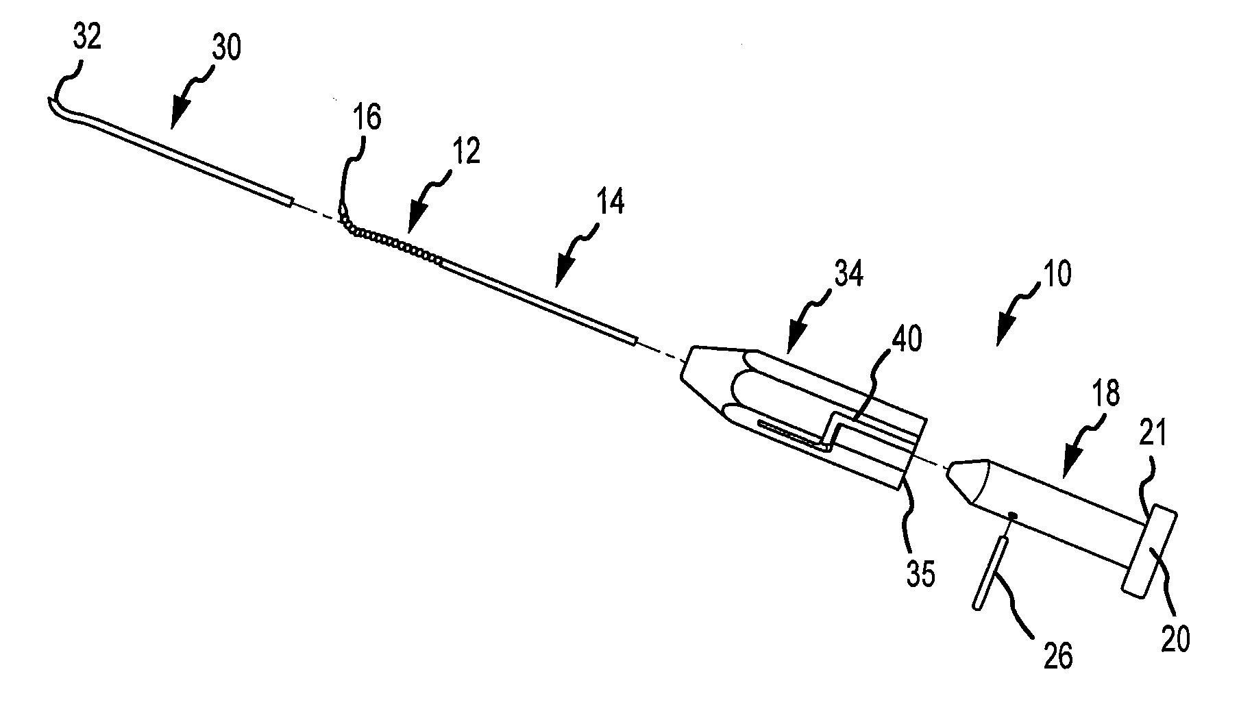
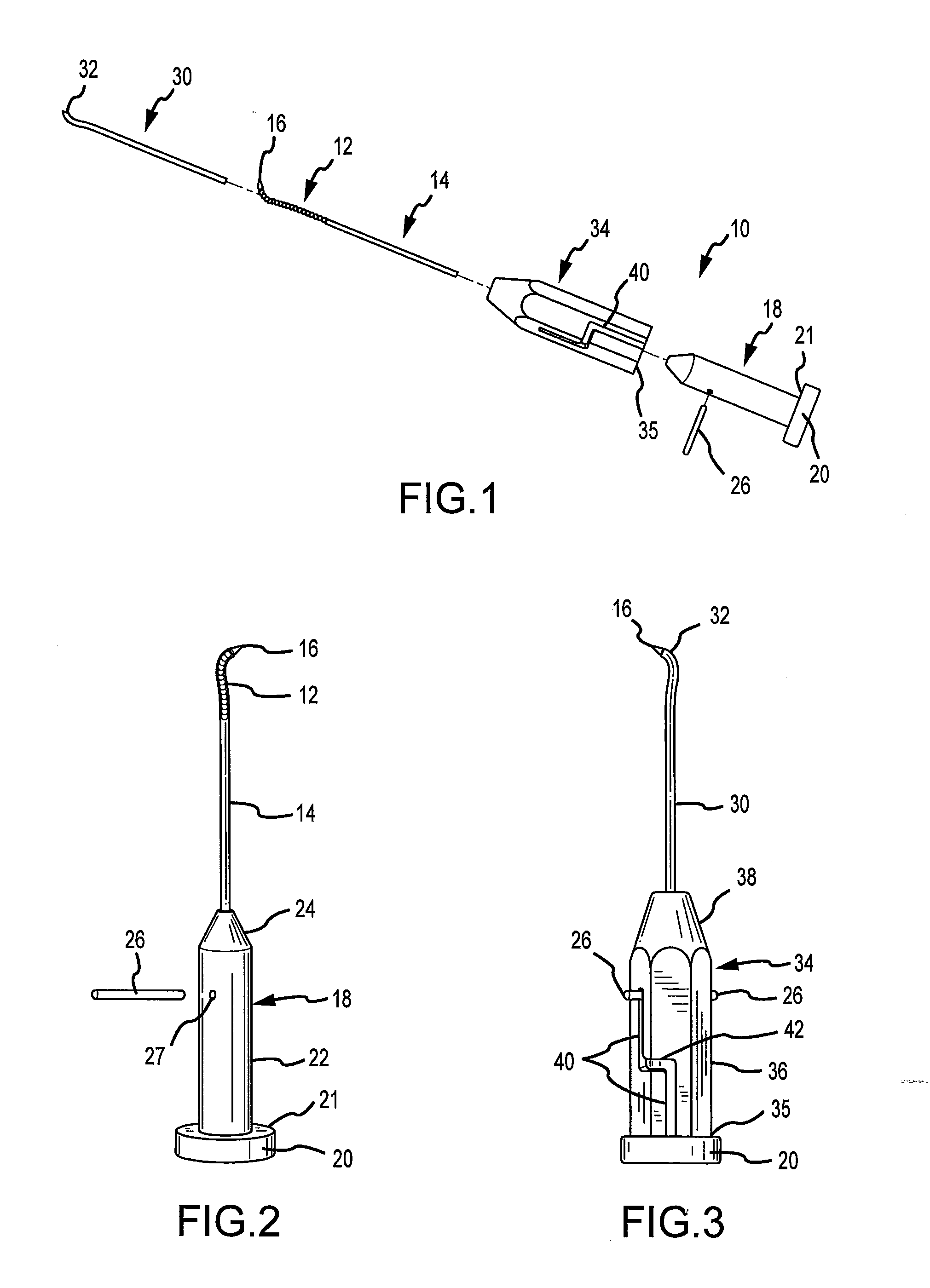
[0026]Referring to FIGS. 1-3, the microfracture awl 10 is illustrated. The microfracture awl 10 includes two subcombinations. The first subcombination comprises an articulating portion 12 of the awl, a rigid shaft 14, and a base 18. The proximal end of the articulating portion 12 connects to a distal end of the rigid shaft 14. The rigid shaft 14 attaches at its proximal end to a distal end of the base 18. The proximal end of the base 18 may include an enlarged portion or cap 20 that is struck by a mallet (not shown) to transfer force through the awl to the bone. The base 18 is shown as having a substantially cylindrical shaped body 22 and a distal converging portion 24. A retention pin opening 27 is formed transversely through the body 22 and receives a retention pin 26. The awl tip 16 of the articulating portion 12 makes contact with and is driven through a targeted subchondral bone plate as explained below.

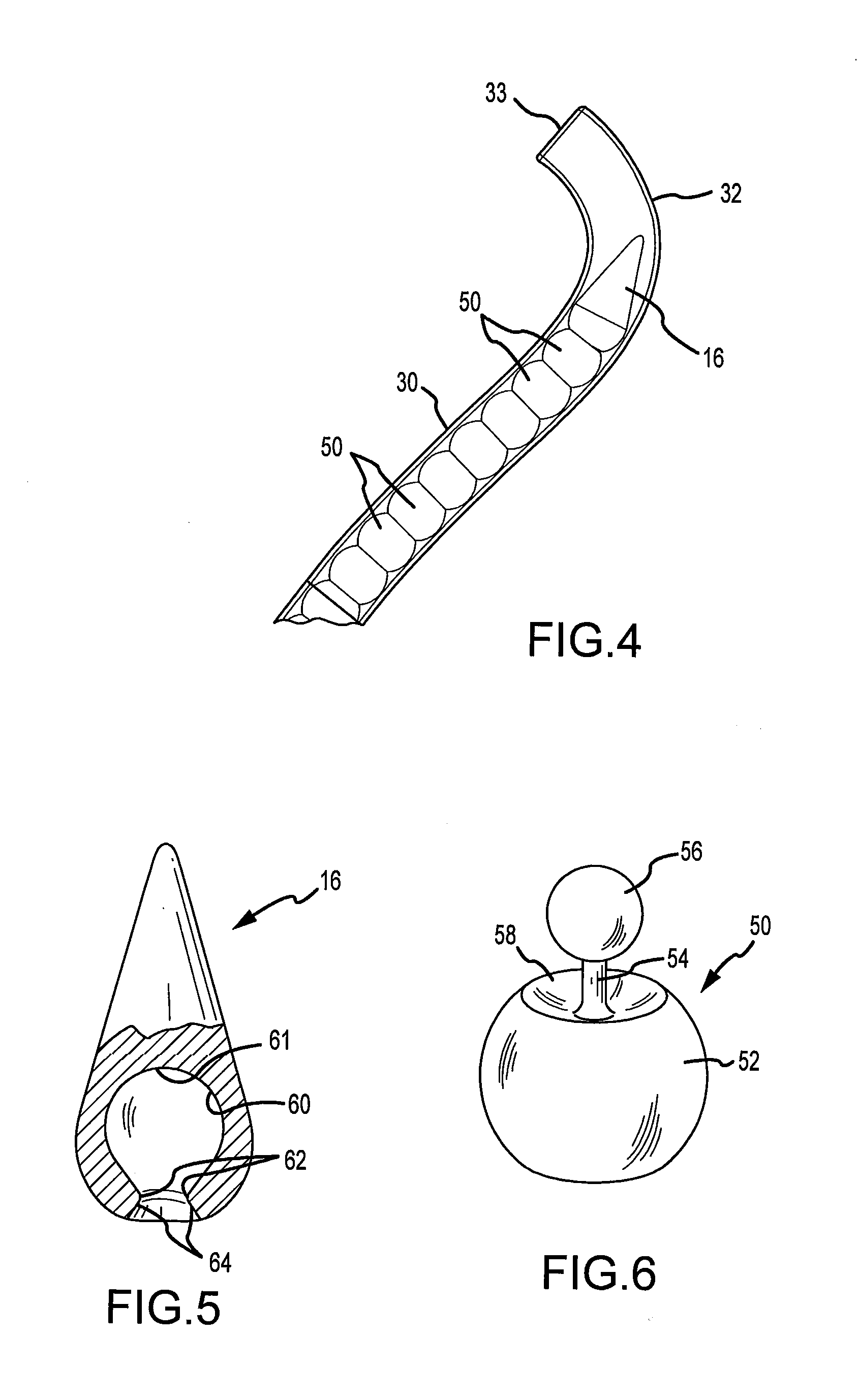
[0027]The second subcombination comprises a guide sleeve 30 having a diamet...


PUM


Abstract

A microfracture awl includes an articulating portion that enables the microfracture awl to strike a subchondral bone plate at a precise desired angle to prevent scuffing or undue scraping of the targeted subchondral bone plate. The articulating portion of the microfracture awl is received through a guide sleeve. A proximal end of the articulating portion is rigid and connects to a base. The articulating portion is placed through a guide sleeve and the base resides in a handle attached to the sleeve. The guide sleeve has a curved distal end. The practitioner strikes the rigid base of the microfracture awl and thereby transmits a force to the articulating portion of the awl however, the force is not transmitted to the guide sleeve or handle. Accordingly, the articulating portion of the awl may smoothly travel through the guide sleeve at the angle defined by the curved distal end of the guide sleeve, thereby angularly positioning the tip of the awl with the targeted bone plate. The articulating portion includes a plurality of articulating members configured in a series of ball and socket configurations. A method includes selection of a guide sleeve with the desired curvature and impacting the awl a number of times at the targeted area to produce a desired effect with respect to the release of bone marrow cells to induce growth of fibrocartilage tissue.

Description

FIELD OF THE INVENTION[0001]The invention relates to an apparatus and method for repairing cartilage in damaged joints, and more particularly, an apparatus and method for conducting microfracture on subchondral bone to repair articular cartilage.BACKGROUND OF THE INVENTION[0002]Articular cartilage is an avascular tissue made of chondrocytes arranged in an extra cellular matrix. Articular cartilage allows for surfaces of abutting bone structures to articulate smoothly with a minimal amount of friction. The cartilage also acts as a means to absorb various forces such as tensile, compressive, and shear forces that are experienced at the joint. Failure of articular cartilage can be a debilitating condition that is very difficult to successfully treat, and results in significant pain for the patient. Because of the inability of articular cartilage to repair as quickly as other tissues such as muscle, damaged articular cartilage often continues to degenerate and progress to conditions suc...

Claims


Application Information

Patent Timeline
IPC IPC(8): A61B17/16A61B17/56
CPCA61B17/1604A61B17/1631A61B2017/1778A61B17/1764A61B17/1675A61B17/1778
Inventor STOLL, E. JORDANJAMES, JEREMY S.
Owner HONDA MOTOR CO LTD
Why Eureka
Try Eureka