
Multi-cylinder piston engine

A piston engine, engine technology, applied in the direction of internal combustion piston engines, combustion engines, engine components, etc., to achieve the effect of lowering the center of gravity

Active Publication Date: 2018-09-28
WARTSILA FINLAND OY
View PDF7 Cites 0 Cited by
  • Summary
  • Abstract
  • Description
  • Claims
  • Application Information

AI Technical Summary

Problems solved by technology

Especially placing a low pressure turbo that is larger and heavier than a high pressure turbo is often problematic

Method used


Image

  • Multi-cylinder piston engine
  • Multi-cylinder piston engine
  • Multi-cylinder piston engine

Examples


no. 1 approach

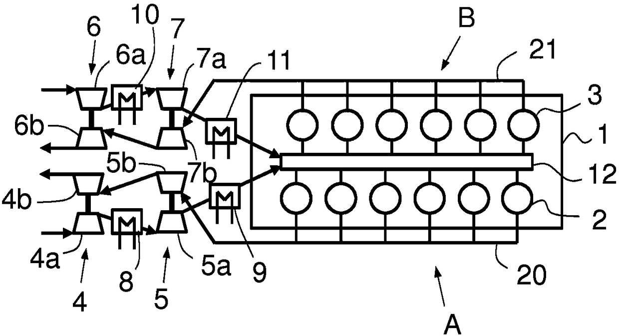
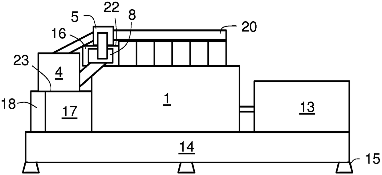
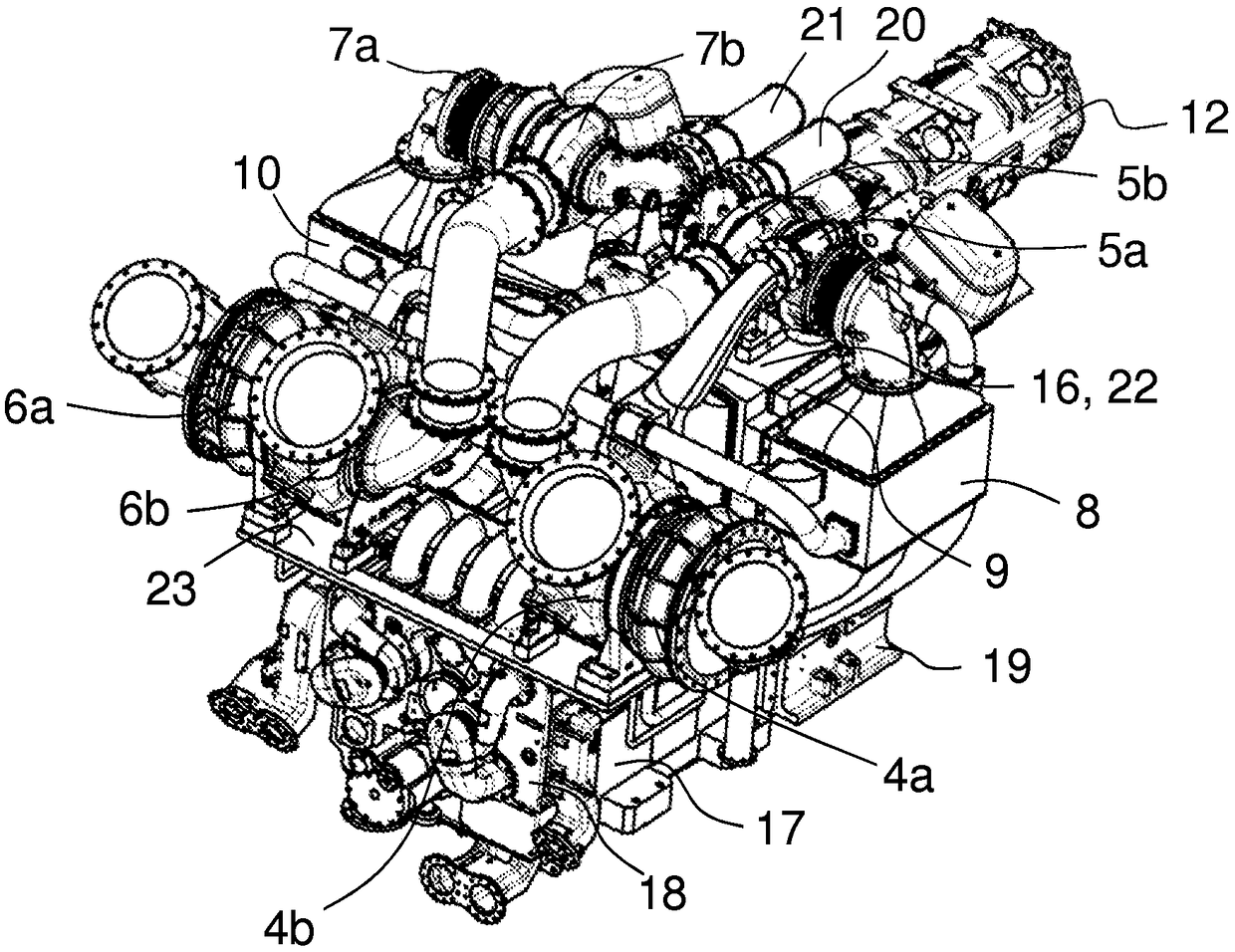
[0031] exist figure 2 , schematically shows figure 1 Side view of engine 1. According to a first embodiment of the invention, the engine 1 comprises a turbocharging system layout. From the direction of column A, engine 1 is shown. The engine 1 is arranged to drive a generator 13 . Engine 1 has a front end and a rear end. The generator 13 is coupled to the rear end of the engine 1 . Thus, the rear end is the flywheel end and drive end of the engine 1 . The front end is the free end. Instead of being coupled to a generator 13 , the engine 1 may be arranged to drive eg a propeller shaft of a ship. According to the invention, the turbochargers 4 , 5 , 6 , 7 of the engine 1 are arranged at the free end of the engine 1 . exist figure 2In , only the turbochargers 4 and 5 on the A-row side of the engine 1 can be seen. The engine 1 and the generator 13 are arranged on the same underframe 14 . The underframe 14 is supported on a floor structure, a ship hull or other similar...


PUM


Abstract

An engine (1) comprises an engine block (19), where cylinders (2, 3) are arranged in a first bank (A) and a second bank (B), a high-pressure turbocharger (5, 7) and a low-pressure turbocharger (4, 6)for each bank (A, B) of the engine, a first turbocharger bracket (16) having a support surface (22) supporting the high- pressure turbochargers (5, 7), and a second turbo-charger bracket (17) that isarranged at the free end of the engine (1) and comprises a support surface (23) supporting the low-pressure turbochargers (4, 6), the support surface (23) being at a lower level than the support surface (22) of the first turbocharger bracket (16).

Description

technical field [0001] The invention relates to a multi-cylinder piston engine according to the preamble of claim 1 . Background technique [0002] Two-stage turbocharging is becoming more and more common in large piston engines such as marine and power station engines. In two-stage turbocharging, two turbochargers are arranged in series. Exhaust gas from the engine is directed to the high-pressure turbocharger, from which it enters the low-pressure turbocharger. The pressure of the intake air is raised to a first level in the low-pressure turbocharger and to a second, higher level in the high-pressure turbocharger. With two-stage turbocharging, the efficiency of the engine is increased because the energy of the exhaust gases is used more efficiently. The two-stage turbocharging also enables higher intake pressures. With higher intake pressure, higher power output can be achieved for a given engine displacement, enabling the use of smaller engines. Additionally, higher ...

Claims


Application Information

Patent Timeline
Patent Type & Authority Applications(China)
IPC IPC(8): F02B37/013F02B67/10F02B37/007F02M35/116
CPCF02B37/007F02B37/013F02B67/10F02M35/116Y02T10/12
Inventor J·图奥米宁T·莱克M·瓦拉斯拖
Owner WARTSILA FINLAND OY
Learn More