Supercharge Your Innovation With Domain-Expert AI Agents!

High-barrier film unit with rotary deviation correcting stretching

A technology of rotating components and units, which is applied in the directions of winding strips, thin material handling, transportation and packaging, etc. It can solve the problems of film deviation, film width cannot be enlarged, and slide down, etc., and achieve the effect of precisely controlling the rotation angle

Pending Publication Date: 2018-10-02
汕头市雅塑机械有限公司
View PDF8 Cites 1 Cited by
  • Summary
  • Abstract
  • Description
  • Claims
  • Application Information

AI Technical Summary

Problems solved by technology

[0002] The rotary stretching device of the traditional plastic film blowing machine is driven by a sprocket, and the fine grinding degree is not high. After the film passes through a nip, it passes through the auxiliary roller and then changes from horizontal to vertical. convert to horizontal
Because this type of rotary stretching adopts vertical film penetration, there are usually guide rollers erected around the rotary frame for guiding when rotating, and the film width cannot be enlarged due to the influence of space.
This method of rotation requires a high degree of elastic tension. If the film is too loose, it will slide down, and if it is too tight, it will affect the stretching deformation, thus affecting the high-quality requirements of the entire production.
And the deflection correction device is separated from the rotary stretching device, and it takes a certain distance for the film to enter the rotary stretching device, which may cause the film to shift after entering

Method used


Image

  • High-barrier film unit with rotary deviation correcting stretching
  • High-barrier film unit with rotary deviation correcting stretching
  • High-barrier film unit with rotary deviation correcting stretching

Examples


Embodiment Construction

[0027] In order to have a further understanding of the purpose, features and functions of the present invention, the preferred embodiments are given in detail with reference to the drawings as follows:

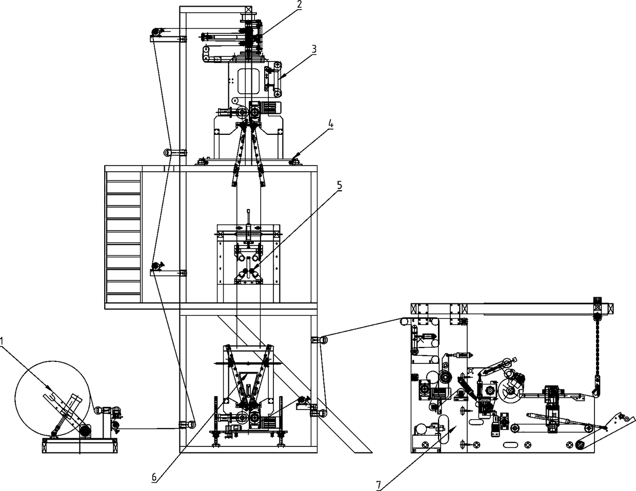
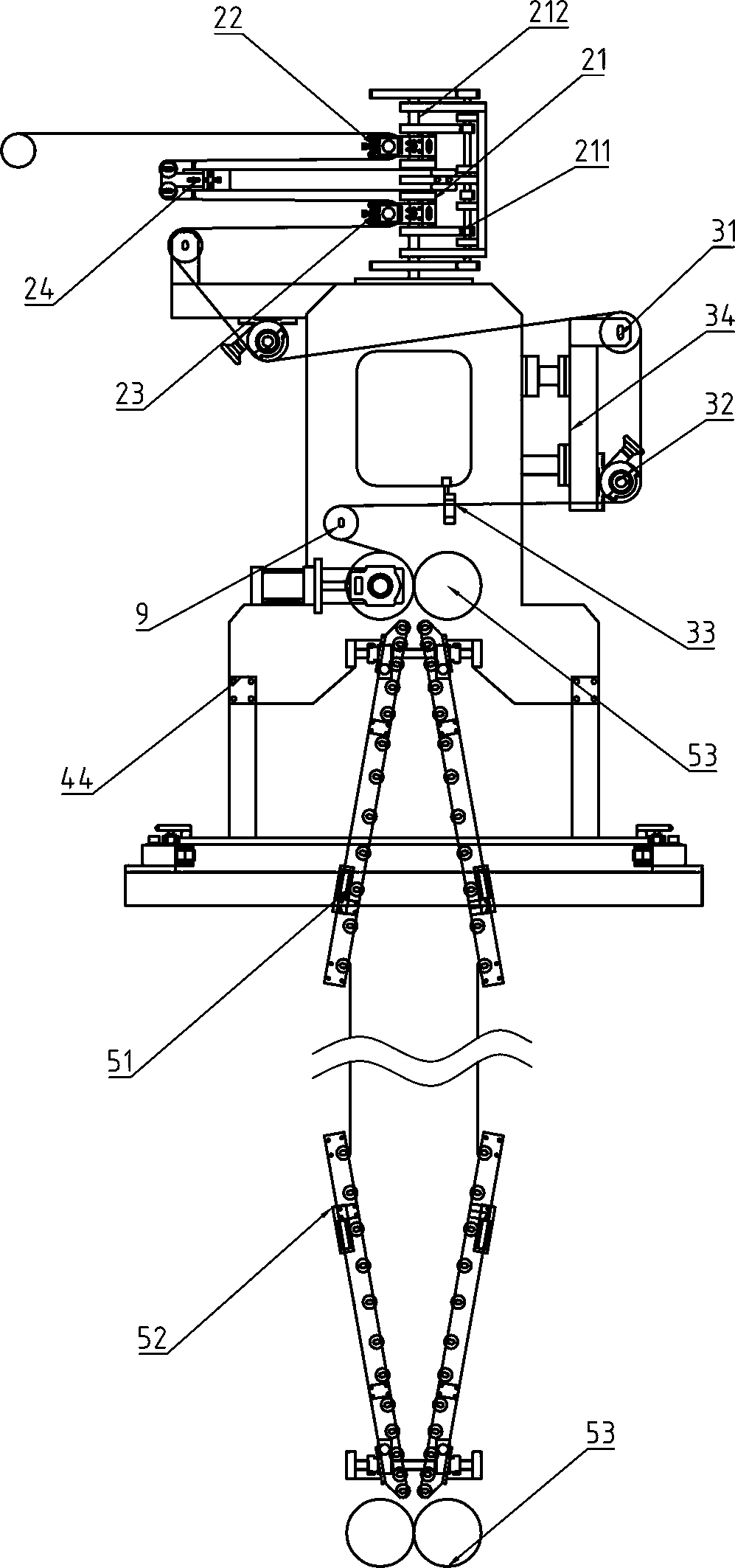
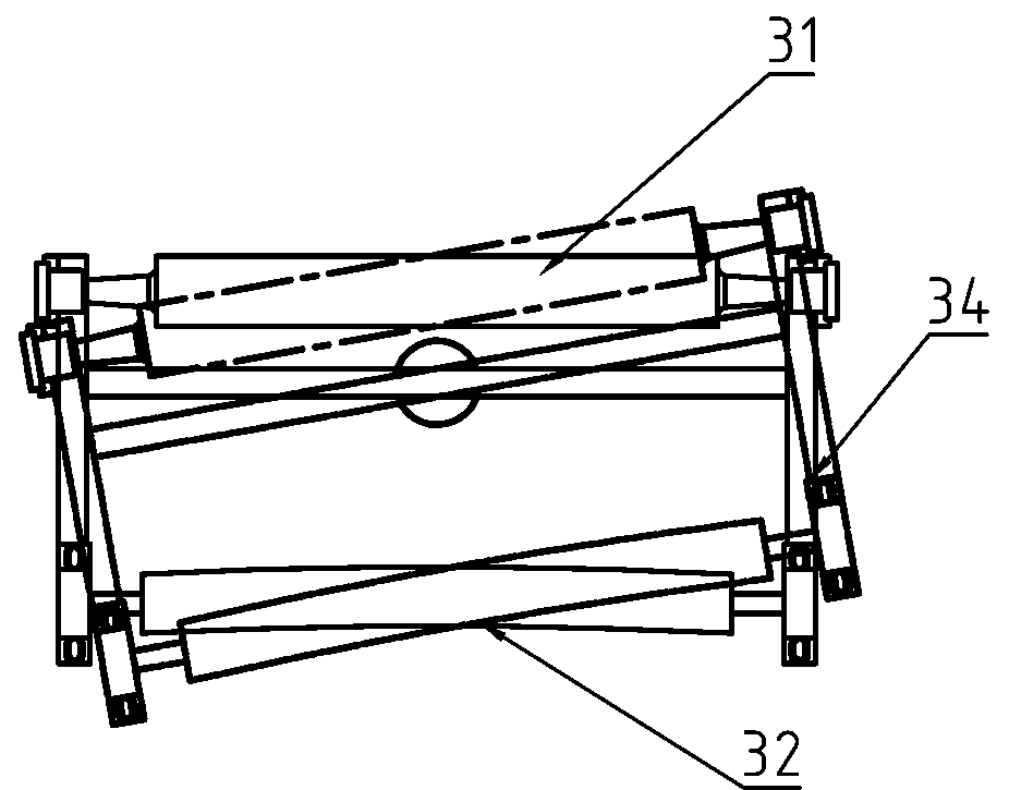
[0028] see Figure 1~7 Shown is a schematic structural diagram of the present invention, a high-resistance diaphragm film unit with rotating deviation correcting and stretching, including: unwinding assembly 1, film rotating assembly 2, deviation correcting assembly 3, rotating base 4, air stamping roller assembly 5, hemming assembly 6 and the winding unit 7, the unwinding assembly 1 and the winding unit 7 are arranged on the front and rear sides of the frame 8, and the high barrier film passes through the film rotating assembly 2, the deviation correcting assembly 3, the air stamping roller assembly 5, the hemming The assembly 6 and the winding unit 7, the film rotating assembly 2 are installed on the top of the frame 8 through the rotating base 4, the air printing roller ass...


PUM


Abstract

The invention relates to the technical field of machine plastic film blowing units, in particular to a high-barrier film unit with rotary deviation correcting stretching. A unwinding assembly is arranged on the front side of the machine frame and a winding unit is arranged on the rear side of the machine frame, and the high-barrier film sequentially passes through a thin film rotating assembly, adeviation correcting assembly, an inflating printing roller assembly, an edge folding assembly and the winding unit; and the thin film rotating assembly is installed on the top of the machine frame through a rotating base, the inflating printing roller assembly is arranged in the middle of the machine frame, and the edge folding assembly is arranged at the bottom of the machine frame. According tothe unit, due to the fact that a gear is adopted for driving, rotating precision is guaranteed by adding a limiting disc, an air cushion roller can adjust to be rotated and stretched by 360 degrees as well, the servo motor is controlled through a PLC, so that the rotating angle can be accurately controlled; the deviation correcting and guiding and the like are realized in a humanized mode, a usercan select a corresponding working mode according to the requirements of different base material or products; and the coiling effect with a larger coiling diameter or a strict surface quality requirement is more obvious.

Description

Technical field: [0001] The invention relates to a plastic film blowing unit, and more specifically relates to a high-barrier film unit with rotation correction and stretching, which is suitable for three-dimensional printing of high-barrier films. Background technique: [0002] The rotary stretching device of the traditional plastic film blowing machine is driven by a sprocket, and the fine grinding degree is not high. After the film passes through a nip, it passes through the auxiliary roller and then changes from horizontal to vertical. to horizontal orientation. Because this type of rotary stretching adopts vertical film penetration, there are usually guide rollers erected around the rotary frame for guiding when rotating, and the film width cannot be enlarged due to the influence of space. This rotation method has high requirements on elastic tension. If the film is too loose, it will slide down, and if it is too tight, it will affect the stretching deformation, thus a...

Claims


Application Information

Patent Timeline
Patent Type & Authority Applications(China)
IPC IPC(8): B65H16/00B65H18/08B65H23/038B65H20/02B65H23/34
CPCB65H16/00B65H18/08B65H20/02B65H23/038B65H23/34B65H2701/1752
Inventor 方汉卫方汉钦
Owner 汕头市雅塑机械有限公司
Features
  • R&D
  • Intellectual Property
  • Life Sciences
  • Materials
  • Tech Scout
  • Unparalleled Data Quality
  • Higher Quality Content
  • 60% Fewer Hallucinations
Learn More