
Spinning rack

A technology of textile frame and heat dissipation mechanism, applied in textile, loom, machine/stand and other directions, can solve the problems of inconvenient transportation and fixation, poor heat dissipation of textile machine, etc., to improve service life, improve cooling and heat dissipation efficiency, guarantee The effect of work efficiency

Inactive Publication Date: 2018-10-02
湖州新爱品纺织有限公司
View PDF9 Cites 2 Cited by
  • Summary
  • Abstract
  • Description
  • Claims
  • Application Information

AI Technical Summary

Problems solved by technology

[0004] In view of this, what this application is to solve is the technical problem of poor heat dissipation of textile machines in the conventional technology, inconvenient transportation and fixing

Method used


Image

  • Spinning rack
  • Spinning rack
  • Spinning rack

Examples


Embodiment Construction

[0021] The implementation of the present application will be described in detail below with reference to the accompanying drawings and examples, so as to fully understand and implement the implementation process of how the present application uses technical means to solve technical problems and achieve technical effects.

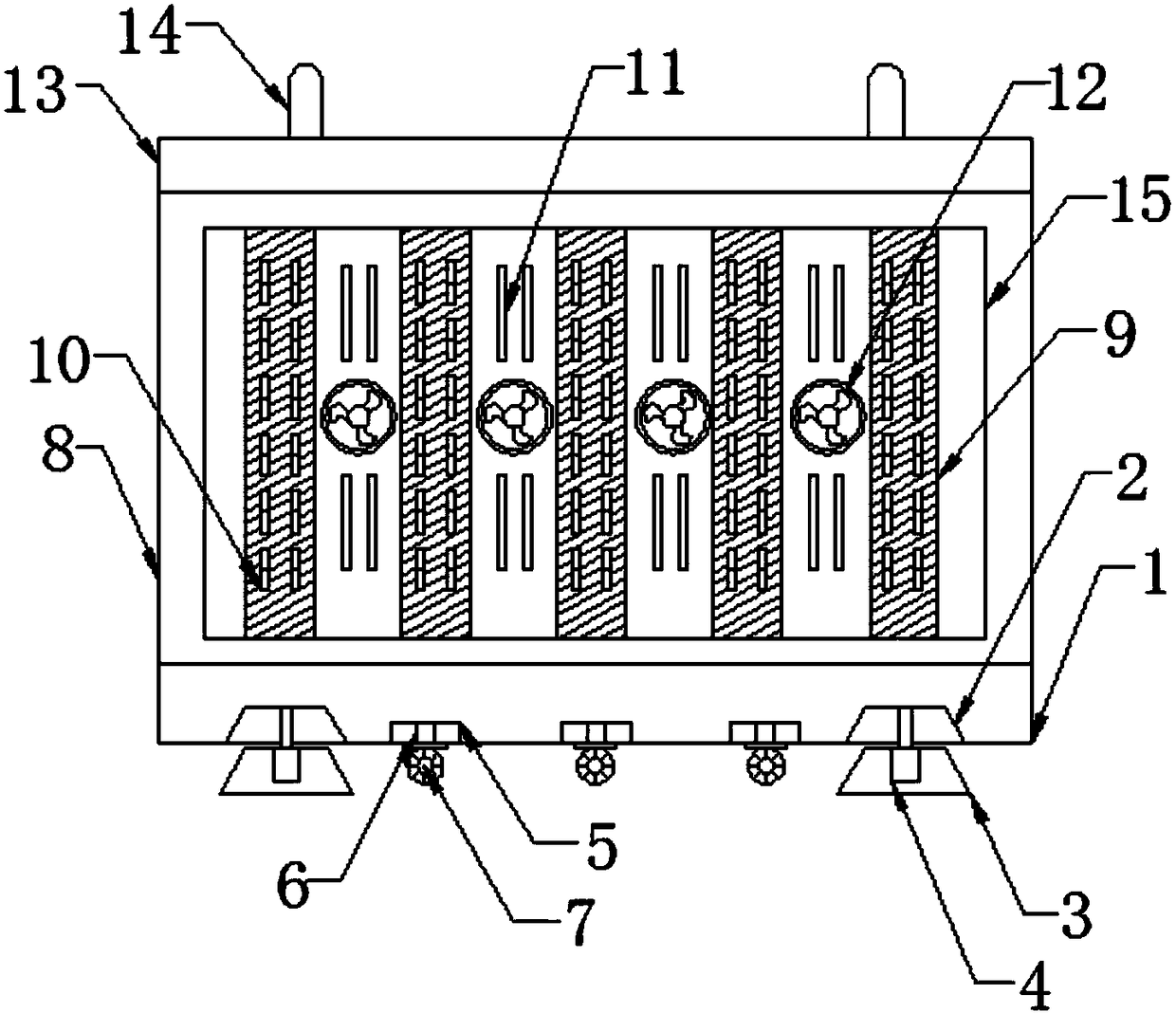
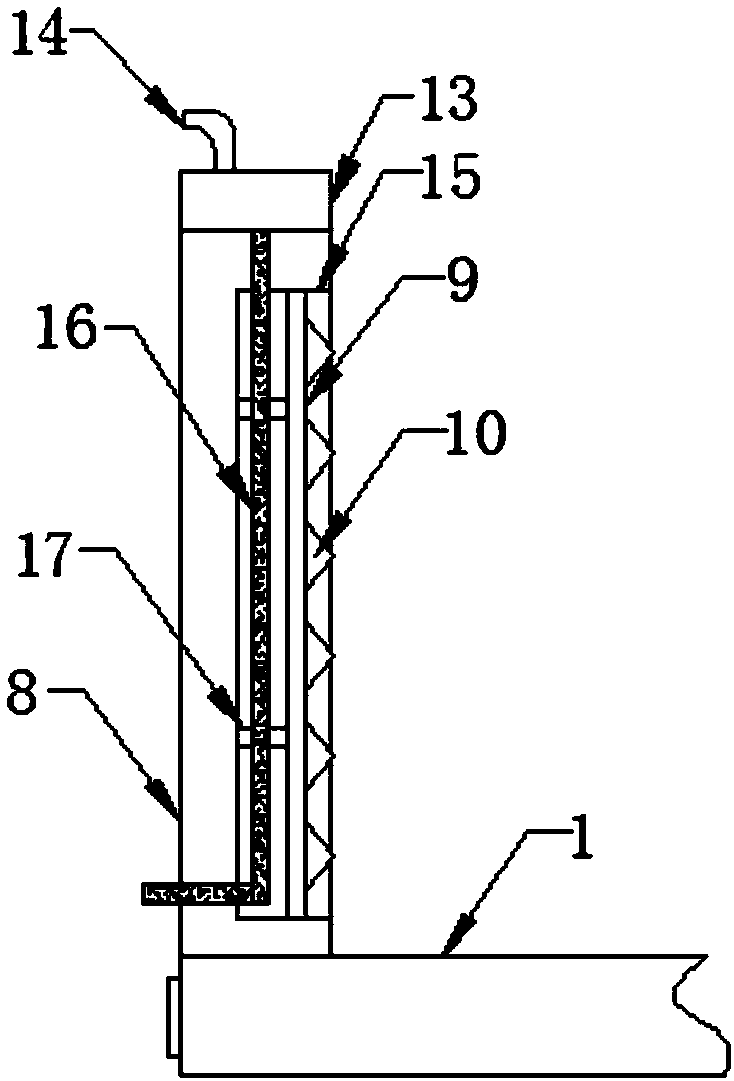
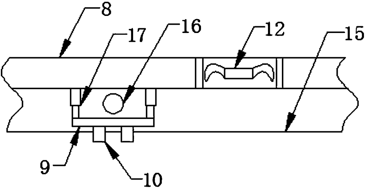
[0022] Such as Figure 1-3 As shown, a textile frame of the present invention includes: a fixed base 1 and a cooling plate 8, the four corners of the bottom of the fixed base 1 are provided with a table-shaped groove 2, the bottom of the table-shaped groove 2 is provided with a fixed table 3, and the top of the fixed table 3 Embedded with a cylinder 4, the output end of the cylinder 4 is fixedly connected to the top inside the table-shaped groove 2, and one side of the top of the fixed base 1 is fixed with a heat dissipation plate 8, and the inside of the heat dissipation plate 8 is provided with a heat dissipation groove 15, and the heat dissipation groove 1...


PUM


Abstract

The invention discloses a spinning rack, comprising a fixing base and a heat-dissipating plate; each of four corners of the bottom end of the fixing base is provided with a terrace-shaped cavity, thebottom of each terrace-shaped cavity is provided with a fixing terrace; a cylinder is embedded onto the top of each fixing terrace; the output end of each cylinder is fixedly connected with the innertop end of the corresponding terrace-shaped cavity; the heat-dissipating plate is fixed to one side of the top end of the fixing base; a heat-dissipating channel is arranged in the heat-dissipating plate; a plurality of heat-dissipating mechanisms are arranged evenly in the heat-dissipating channel; a plurality of suction fans are embedded evenly in the middle of the inner wall of one side of theheat-dissipating channel. The fixing terraces at the bottom of the fixing base are used with the cylinders such that stability of a spinning machine can be improved and the spinning machine can be fixed conveniently at any time; wheels help conveniently move the spinning machine; the heat-dissipating mechanisms provide quick heat dissipation and cooling for a spinning machine body, operating efficiency of the spinning machine is ensured, and service life of the spinning machine is extended.

Description

technical field [0001] The application belongs to a frame, in particular, relates to a textile frame. Background technique [0002] Textile machine, also known as textile machine, loom, cotton spinning machine, etc., the ancient textile machine is a loom driven by manpower. The textile machine is the full name of the tool that processes raw materials such as thread, silk, and hemp into silk and then weaves them into cloth. Such as spinning pendants, spinning wheels, spindles, pedal looms, modern mechanical looms, modern numerically controlled automatic looms, etc. [0003] At present, the volume of modern textile machines is relatively large, and they are relatively inflexible for transportation and fixing, which brings difficulties to use, and the working hours of textile machines are relatively long. Because they are in high-temperature factories, the heat dissipation is not good. It will reduce the working efficiency of the equipment, easily cause damage to the equipment...

Claims


Application Information

Patent Timeline
Patent Type & Authority Applications(China)
IPC IPC(8): D03D49/02F16M11/22F16M11/04D03J1/00
CPCD03D49/02D03J1/008F16M11/04F16M11/22
Inventor 石阿金
Owner 湖州新爱品纺织有限公司
Learn More