Mounting structure for fabricated wall of building

A technology for installing structures and walls, applied to building components, building structures, buildings, etc., can solve problems such as troublesome installation and removal, looseness that cannot be adjusted, and weak installation, etc., to achieve convenient installation and removal, firm and stable installation structure, and guarantee The effect of installation quality

Active Publication Date: 2018-10-02
东莞市中泰建安工程有限公司
View PDF5 Cites 5 Cited by
  • Summary
  • Abstract
  • Description
  • Claims
  • Application Information

AI Technical Summary

Problems solved by technology

[0004] The object of the present invention is to provide a building assembly wall installation structure, through the use of the installation frame, support mechanism and positioning mechanism, the wall installation structure can further strengthen the installed wall during use, and the installation and removal structure is simple , to solve the problem that the existing splicing wall panels are not installed firmly during the installation process, loose and cannot be adjusted after the installation is completed and during the installation process, low work efficiency, high cost, large space occupation, and troublesome installation and removal

Method used


Image

  • Mounting structure for fabricated wall of building
  • Mounting structure for fabricated wall of building
  • Mounting structure for fabricated wall of building

Examples


Embodiment Construction

[0031] The following will clearly and completely describe the technical solutions in the embodiments of the present invention with reference to the accompanying drawings in the embodiments of the present invention. Obviously, the described embodiments are only some, not all, embodiments of the present invention. Based on the embodiments of the present invention, all other embodiments obtained by persons of ordinary skill in the art without creative efforts fall within the protection scope of the present invention.

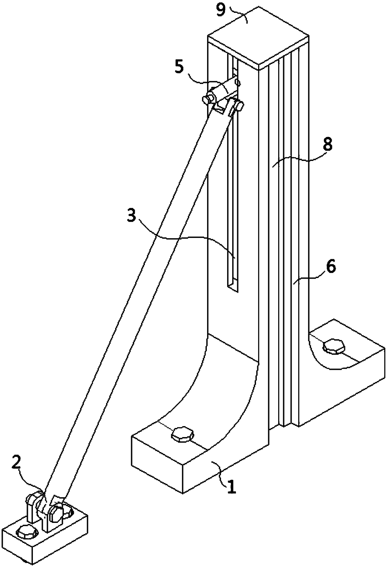
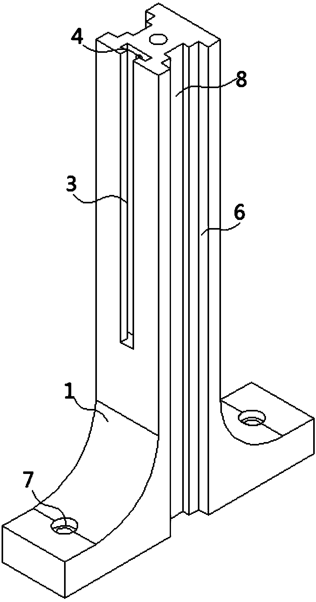
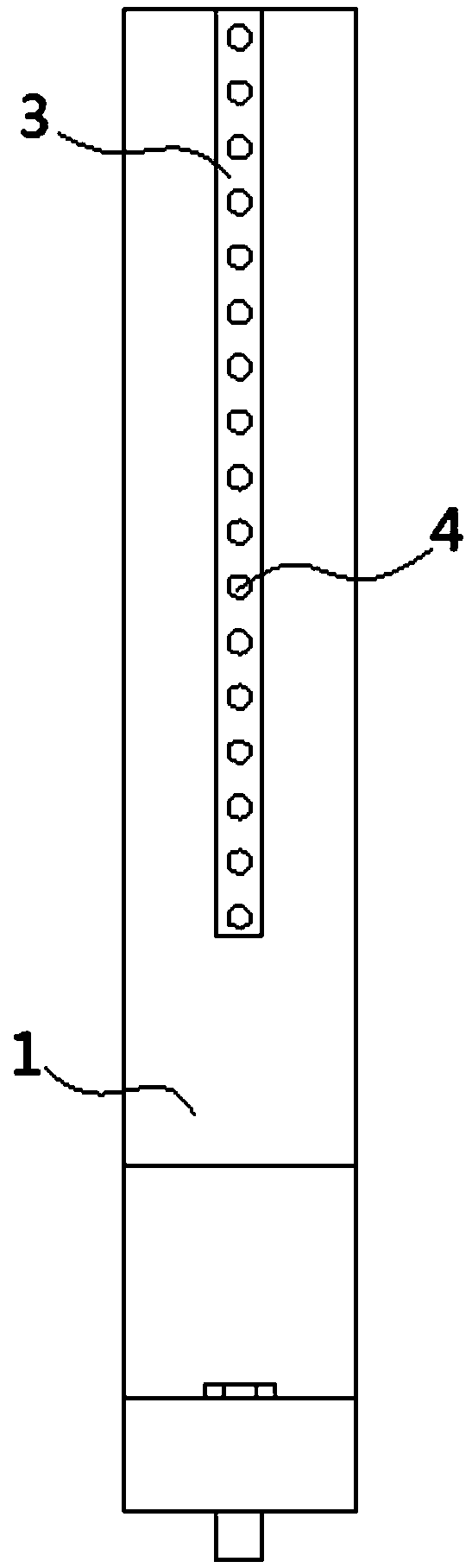
[0032] see Figure 1-7 As shown, the present invention is a building assembly wall installation structure, comprising a mounting frame 1 and a supporting mechanism 2, characterized in that: a surface of the mounting frame 1 is provided with a chute 3, and the bottom of the chute 3 is provided with a positioning hole 4, The inside of the chute 3 is slidably fitted with a positioning mechanism 5, and one side of the positioning mechanism 5 is rotationally connected w...


PUM


Abstract

The invention discloses a mounting structure for a fabricated wall of a building and relates to the technical field of wall mounting structures. The mounting structure comprises a mounting frame and asupporting mechanism. A sliding groove is formed in one surface of the mounting frame, and positioning holes are formed in the bottom of the sliding groove; the interior of the sliding groove is in sliding fit with a positioning mechanism, one side of the positioning mechanism is rotatably connected with the supporting mechanism through a cylindrical pin, and grooves are formed in the two opposite faces of the mounting frame correspondingly; mounting holes are formed in the bottom of the mounting frame; and the positioning mechanism comprises a sliding block, and a connecting block and a spring sleeve are fixed to one surface of the sliding block. By using the mounting frame, the supporting mechanism and the positioning mechanism, the loosening and inclined wall can be adjusted in time when the wall is mounted through the mounting structure; the mounting structure is firm and stable, and thus the mounting quality and the service life of the wall are ensured; and mounting and dismantling are convenient, recycling can be achieved, damaged parts can be replaced in time, the working efficiency is improved, and the economic benefits are increased.

Description

technical field [0001] The invention belongs to the technical field of wall installation structures, in particular to a building assembly wall installation structure. Background technique [0002] At present, fewer and fewer brick-concrete structures are used in many wholesale markets, factories, farms and other places, and more and more steel structures are used. After the main frame of the steel structure is erected, the frame is often filled by stacking aerated bricks. This requires processing concrete on site, or transporting concrete from the mixing station to the construction site by tank truck. Both methods increase the pollution to the environment. At the same time, the price of aerated bricks is relatively high, which increases the construction cost. [0003] At present, spliced ​​wall panels are mostly used for filling the frame, which is efficient and fast, does not use concrete, has no pollution to the environment, and is low in cost. However, when the spliced ​​...

Claims


Application Information

Patent Timeline
Patent Type & Authority Applications(China)
IPC IPC(8): E04B2/74
CPCE04B2/7407E04B2/7433
Inventor 卓菁
Owner 东莞市中泰建安工程有限公司
Why Eureka
Try Eureka