Drilling device for water conservancy project construction

A technology of water conservancy engineering and perforating device, which is applied in the agricultural field, can solve the problems of easy backfilling of soil into holes and poor stability, and achieve the effects of improving strength, improving stability and improving stability.

Inactive Publication Date: 2018-10-02
安徽智联管理咨询有限公司
View PDF1 Cites 1 Cited by
  • Summary
  • Abstract
  • Description
  • Claims
  • Application Information

AI Technical Summary

Problems solved by technology

[0003] The purpose of the present invention is to solve the problems that existing punching devices for water conservancy construction have poor stability during the punching process, cannot be applied to different working environments, and the soil that is punched out is easy to be backfilled into the hole. A drilling device for water conservancy construction with reasonable structural design, good quality and performance, no backfilling of the drilled soil into the hole, multi-angle drilling, wide application range, and high stability

Method used


Image

  • Drilling device for water conservancy project construction
  • Drilling device for water conservancy project construction
  • Drilling device for water conservancy project construction

Examples


Embodiment 1

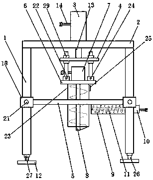
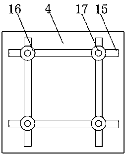
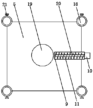
[0018] as attached Figure 1-3 Shown: a drilling device for water conservancy construction, including a vertical bar 1, a top plate 2, a cylinder 3, an adjustment plate 4, a limit plate 5, a fixed plate 6, a motor 7, a drilling column 8, and a soil discharge tank 9 , motor two 10, auger 11 and backing plate 12, it is characterized in that: described top plate 2 is arranged on the vertical bar 1, and described cylinder 3 is arranged on the top plate 2, and is provided with power line 14 on cylinder 3 , Piston rod 13, described adjusting plate 4 is arranged on the piston rod 13, and is provided with positioning groove 15 on adjusting plate 4, is provided with connecting rod 17 by positioning nut 16 in described positioning groove 15, described Limiting ring 18 is set on the limiting plate 5, limiting groove 19 is set at the center of limiting plate 5, soil falling groove 20 is arranged on one side of limiting groove 19, and limiting ring 18 is arranged on On the vertical rod 1,...

Embodiment 2

[0024] as attached Figure 4 Shown: a drilling device for water conservancy construction, including a vertical bar 1, a top plate 2, a cylinder 3, an adjustment plate 4, a limit plate 5, a fixed plate 6, a motor 7, a drilling column 8, and a soil discharge tank 9 , motor two 10, auger 11 and backing plate 12, it is characterized in that: described top plate 2 is arranged on the vertical bar 1, and described cylinder 3 is arranged on the top plate 2, and is provided with power line 14 on cylinder 3 , Piston rod 13, described adjusting plate 4 is arranged on the piston rod 13, and is provided with positioning groove 15 on adjusting plate 4, is provided with connecting rod 17 by positioning nut 16 in described positioning groove 15, described Limiting ring 18 is set on the limiting plate 5, limiting groove 19 is set at the center of limiting plate 5, soil falling groove 20 is arranged on one side of limiting groove 19, and limiting ring 18 is arranged on On the vertical rod 1, t...


PUM


Abstract

The invention discloses a drilling device for water conservancy project construction. The drilling device comprises a vertical rod, a top plate, a cylinder, an adjusting plate, a limiting plate, a fixing plate, a first motor, a drilling column, a soil discharging groove, a second motor, a packing auger and a backing plate. The drilling device is characterized in that the top plate is arranged on the vertical rod, the cylinder is arranged on the top plate, the adjusting plate is arranged on a piston rod, a connecting rod is arranged in the positioning groove through a positioning nut, a limiting ring is arranged on the limiting plate, a connecting plate and a soil lifting cylinder are arranged on the fixing plate, the first motor is arranged on the fixing plate, and the drilling column is arranged in the soil lifting cylinder. According to the drilling device, the connecting rod is a structure which can adjust a position in the positioning groove through the positioning nut, by adjusting the position of the connecting rod in the positioning groove, the angle between the fixing plate and the adjusting plate can be adjusted, so that the drilling column can drilling soil at different angles, meet the needs of different water conservancy projects, and expand the application range of the drilling device.

Description

technical field [0001] The invention relates to the field of agricultural technology, in particular to a drilling device for hydraulic engineering construction. Background technique [0002] During the construction of water conservancy projects, it is often necessary to drill holes. During the drilling process, the drilled soil is easy to backfill into the holes, which reduces the quality and efficiency of drilling, and increases the labor intensity of operators. For example, the application number is 201710327122.5 The patent disclosed a combined punching device for water conservancy construction, which solves the problem of low drilling efficiency of existing punching machines, but it has the disadvantages of poor stability and inability of the punching device during the punching process. It is suitable for different working environments and the problem that the soil drilled out is easy to be backfilled into the hole. Contents of the invention [0003] The purpose of th...

Claims


Application Information

Patent Timeline
Patent Type & Authority Applications(China)
IPC IPC(8): E21B3/02E21B7/04E21B7/00E21B15/04
CPCE21B3/02E21B7/005E21B7/04E21B15/04
Inventor 卢国孝汪致闻
Owner 安徽智联管理咨询有限公司
Why Eureka
Try Eureka