Filtering magnetic core with high magnetic conductivity

A technology with high magnetic permeability and magnetic core, which is applied in the field of filtering and can solve the problems of electromagnetic field influence and affecting filter filtering effect

Active Publication Date: 2020-11-24
ANHUI HUALIN MAGNETIC TECH
View PDF15 Cites 0 Cited by
  • Summary
  • Abstract
  • Description
  • Claims
  • Application Information

AI Technical Summary

Problems solved by technology

[0002]The filter is usually composed of a capacitor, an inductor and a resistor. The inductor is also an electromagnetic coil. On the insulating tube, when a current flows through the wire, a certain electromagnetic field will be generated around the wire, but the wire will generate heat when the current passes through the wire, and the electromagnetic field will be affected as the temperature rises, thereby affecting filter effect

Method used


Image

  • Filtering magnetic core with high magnetic conductivity
  • Filtering magnetic core with high magnetic conductivity
  • Filtering magnetic core with high magnetic conductivity

Examples


Embodiment 1

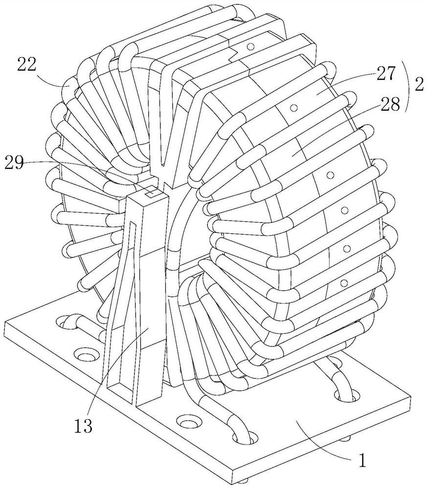
[0037] Such as Figure 1 to Figure 3 As shown, the present invention provides a filter core with high magnetic permeability, including: a base 1, on which a cooling fan 11 is arranged; a housing 2, which is detachably connected to the base 1, the housing 2 is provided with a heat dissipation chamber 21, and a coil 22 is wound on the outside of the housing 2, and the housing 2 is provided with an air inlet 23 and an air vent communicating with the heat dissipation chamber 21 24, the vent 24 communicates with the air intake of the heat dissipation fan 11; the filter element 4, the filter element 4 is detachably arranged between the air intake 24 and the air intake, the The filter element 4 is provided with a dust collection groove 41 with an opening facing the air vent 24 .

[0038] It can be understood that, by making the air suction port of the heat dissipation fan 11 communicate with the heat dissipation chamber 21, when the heat dissipation fan 11 is running, under the acti...

Embodiment 2

[0041] The difference between this embodiment and the foregoing embodiments is that;

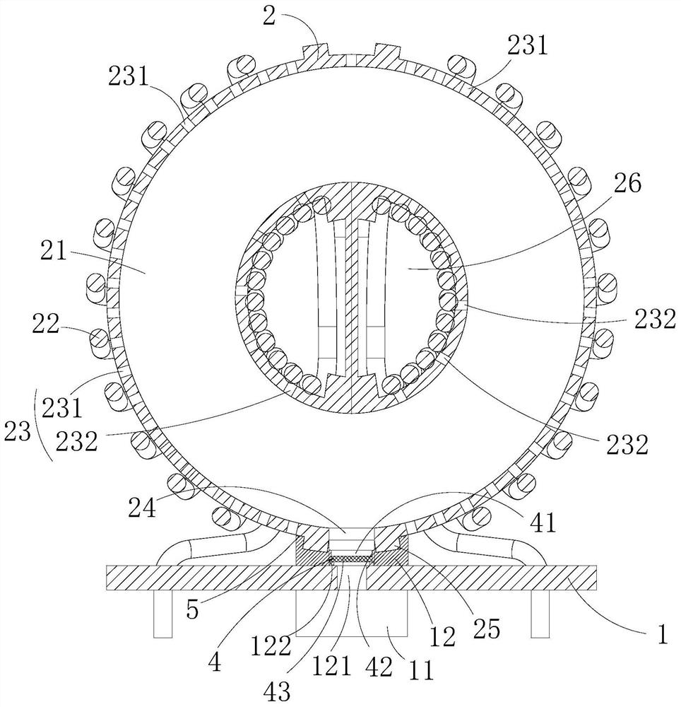
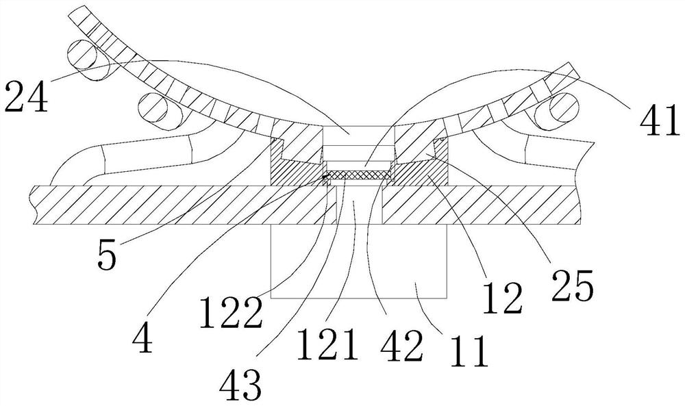
[0042] Such as Figure 1 to Figure 3 As shown, in some embodiments of the present invention, the heat dissipation fan 11 is arranged at the lower end of the base 1, and the upper end of the base 1 is provided with a boss 12, and the boss 12 is provided with an overflow channel 121 , the upper port of the flow passage 121 communicates with the vent 24, and the suction port communicates with the lower port of the flow passage 121; wherein, the filter element 4 is arranged in the flow passage Inside Road 121. Thereby, communication between the air intake port and the vent port 24 is facilitated.

[0043] In some embodiments of the present invention, the filter element 4 includes a dust collection cylinder 42 and a filter screen 43 connected to the lower end of the dust collection cylinder 42 , the inner cavity of the dust collection cylinder 42 and the filter screen 43 The dust collection gr...

Embodiment 3

[0047] The difference between this embodiment and the foregoing embodiments is that;

[0048] Such as Figure 1 to Figure 3 As shown, in some embodiments of the present invention, the housing 2 is provided with a central hole 26, the coil 22 is passed through the central hole 26, and the air inlet 23 includes a plurality of The first air inlet hole 231 on the side wall of the housing 2 and a plurality of second air inlet holes 232 arranged at intervals on the side wall of the central hole 26 . Thus, it is ensured that the airflow from all places can enter into the cooling chamber 21 to improve the cooling effect.

[0049] In some embodiments of the present invention, at least a part of the first air inlet hole 231 is located between two adjacent coils 22 . Thus, the heat dissipation effect is improved. It should be noted that the coil 22 is composed of wires, and the first air inlet hole 231 may be located between two adjacent wires.

[0050] In some embodiments of the pres...


PUM


Abstract

The invention provides a filtering magnetic core with high magnetic conductivity, wherein the filtering magnetic core comprises a base, a shell and a filtering piece; the base is provided with a heatdissipation fan; the shell is detachably connected to the base, a heat dissipation cavity is formed in the shell, a coil is wound around the outer portion of the shell, an air inlet and a ventilationopening which are communicated with the heat dissipation cavity are formed in the shell, and the ventilation opening is communicated with an air suction opening of the heat dissipation fan; the filtering piece is detachably arranged between the ventilation opening and the air suction opening, and a dust collecting groove with an opening facing the ventilation opening is formed in the filtering piece. An air suction port of a heat dissipation fan is communicated with the heat dissipation cavity; air flow enters the shell from the outer side of the shell, so heat generated by the coil enters theheat dissipation cavity along with flowing of the air flow, the air flow with the heat in the heat dissipation cavity flows out of the shell through the heat dissipation fan to form circulation of the air flow, it is guaranteed that the heat generated by the coil can be taken away by the air flow, and the purpose of cooling the coil is achieved.

Description

technical field [0001] The invention relates to the field of filter technology, in particular to a filter core with high magnetic permeability. Background technique [0002] Filters are usually composed of capacitors, inductors and resistors. Inductors are also electromagnetic coils. The coils in the prior art are usually made of wires that are wound round by round on the insulating tube. When there is current flowing through the wires, it will A certain electromagnetic field is generated around this wire, but when the current passes through the wire, the wire will generate heat, and as the temperature rises, it will affect the electromagnetic field, thereby affecting the filtering effect of the filter. [0003] Therefore, it is necessary to develop a filter core with high permeability to solve the above technical problems. Contents of the invention [0004] The purpose of the present invention is to provide a filter core with high magnetic permeability, so as to cool dow...

Claims


Application Information

Patent Timeline
Patent Type & Authority Applications(China)
IPC IPC(8): H01F27/08H01F27/02B01D46/10
CPCH01F27/085H01F27/025B01D46/10Y02E40/40
Inventor 沈宏江蔡忠贤张学舟
Owner ANHUI HUALIN MAGNETIC TECH
Why Eureka
Try Eureka