Vacuum-pumping system for wind tunnel body

A vacuum system and cavity technology, which is applied in aerodynamic tests, measuring devices, instruments, etc., can solve the problems of pump and motor load increase, achieve the effect of small airflow resistance, improve heat dissipation efficiency, and ensure stability

Active Publication Date: 2016-01-06
ZHEJIANG VACUUM EQUIP GROUP
View PDF6 Cites 12 Cited by
  • Summary
  • Abstract
  • Description
  • Claims
  • Application Information

AI Technical Summary

Problems solved by technology

[0009] The exhaust port size of the overflow valve of the Roots pump in this system is matched with the pump, and the valve core guide, sealing, and weight proble

Method used


Image

  • Vacuum-pumping system for wind tunnel body
  • Vacuum-pumping system for wind tunnel body
  • Vacuum-pumping system for wind tunnel body

Examples


Embodiment Construction

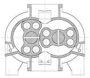
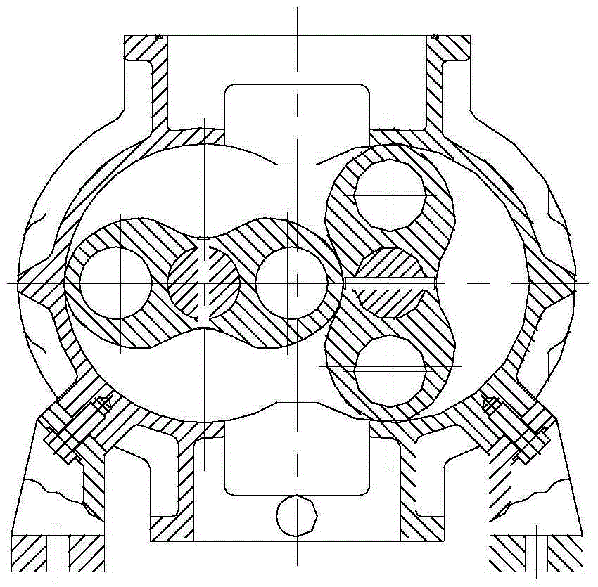
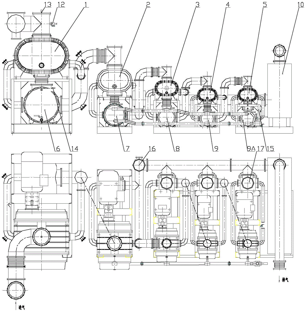
[0026] The wind tunnel body vacuum pumping system of the present invention is composed of a first-stage Roots pump 1, a second-stage Roots pump 2, a third-stage Roots pump 3, a fourth-stage Roots pump 4, a Five-stage Roots pump 5 connected in series to form a vacuum pumping unit. According to the needs, the system is also equipped with a first-stage heat exchanger 6, a second-stage heat exchanger 7, a third-stage heat exchanger 8, a fourth-stage heat exchanger 9, and a fifth-stage heat exchanger 9A , A muffler 10 forms.

[0027] The working principle of the present invention is as follows: the pumped gas passes through the first-stage Roots pump 1, the second-stage Roots pump 2 to the third-stage Roots pump 3, when the pressure at the inlet of the third-stage Roots pump 3 is higher than the exhaust pressure of the unit , then part of the pumped gas is directly discharged into the muffler through the overflow valve 16, and is directly discharged into the atmosphere through the...


PUM


Abstract

The invention relates to a vacuum-pumping system for a wind tunnel body. The vacuum-pumping system includes a multi-level air cooled lobe pump assembly, a set of heat exchangers, a silencer, an overflow valve, and a check valve; the upper part of each air cooled lobe pump is provided with an air inlet, and the lower part of each air cooled lobe pump is provided with an air outlet; two sides of each air cooled lobe pump are provided with a cool air returning opening respectively, so that heat balance of a pump body can be maintained when the pump operates under a high pressure difference; when the pressure of an air inlet connected to the back end of the lobe pump system is greater than the discharge pressure of the lobe pump assembly, a part of pumped air can be directly discharged into the silencer via the overflow valve, and then is discharged into the atmosphere via the silencer; the other part of the pumped air is discharged into the atmosphere via the overflow valve and the silencer. Each vacuum heat exchanger of the system mainly includes a housing, heat exchanger tubes, and an anti-reflux valve. A PLC control technology and a frequency converter technology are adopted by the system, so that the vacuum-pumping system can automatically adjust the pumping speed according to the pressure of an entrance.

Description

technical field [0001] The invention relates to a vacuum pumping system for a wind tunnel body, in particular to a vacuum pumping system for a wind tunnel body using a large, high-pressure-difference-resistant air-cooled Roots vacuum pump. Background technique [0002] Roots pumps are widely used in vacuum degassing, vacuum smelting, vacuum treatment of molten steel in the vacuum metallurgical industry, as well as vacuuming non-corrosive gases in devices such as space simulation and low-density wind tunnels. It can also be used in production processes such as distillation, evaporation, and drying in industries such as chemical, food, pharmaceutical, and electrical appliances. [0003] The structure of Roots vacuum pump is composed of pump housing, rotor and transmission part. There is a certain gap between the rotor of the pump and the rotor and the pump casing, and the gap value and relative rotation position are guaranteed by the high machining accuracy and synchronous sp...

Claims


Application Information

Patent Timeline
IPC IPC(8): G01M9/04
Inventor 王西龙许涛王贵钟云会陈连忠李志远高逊懿蒋招巧周君斐李锦卫
Owner ZHEJIANG VACUUM EQUIP GROUP
Why Eureka
Try Eureka