Damping type engine support

A technology of engine bracket and shock absorber, which is applied in the direction of engine frame, spring/shock absorber, supporting machine, etc., can solve the problems of loose connection between engine and engine bracket, affecting engine space utilization, rubber sleeve deformation, etc., to achieve Good shock absorption effect, guaranteed performance and extended service life

Inactive Publication Date: 2018-10-02
ANHUI SIYUAN SANQING INTELLIGENT MFG CO LTD
View PDF7 Cites 3 Cited by
  • Summary
  • Abstract
  • Description
  • Claims
  • Application Information

AI Technical Summary

Problems solved by technology

The engine is accompanied by different degrees of vibration during the working process. The engine bracket has been working in such a very harsh environment, so the engine and the engine bracket need to be fixed and stable; and the existing engine and the engine bracket Usually, a rubber sleeve is provided for shock absorption, but the connection between the engine and the engine bracket must be tightened during the installation process, which will inevitably cause deformation of the rubber sleeve, so the cushioning and shock absorption effect of the rubber sleeve is at the beginning of installation. It is reduced to a certain extent, and at the same time, the vibration of the engine will accelerate the cracking and aging of the rubber sleeve. After the rubber sleeve is damaged, the connection between the engine and the engine bracket will become loose, which will cause a series of problems; and use rubber at the connection The sleeve will also affect the utilization of the engine space to a certain extent, and it is not easy to assemble

Method used


Image

  • Damping type engine support
  • Damping type engine support
  • Damping type engine support

Examples


Embodiment Construction

[0016] It should be noted that, in the case of no conflict, the embodiments of the present invention and the features in the embodiments can be combined with each other.

[0017] In describing the present invention, it should be understood that the terms "center", "longitudinal", "transverse", "upper", "lower", "front", "rear", "left", "right", " The orientations or positional relationships indicated by "vertical", "horizontal", "top", "bottom", "inner" and "outer" are based on the orientations or positional relationships shown in the drawings, and are only for the convenience of describing the present invention and Simplified descriptions, rather than indicating or implying that the device or element referred to must have a particular orientation, be constructed and operate in a particular orientation, and thus should not be construed as limiting the invention. In addition, the terms "first", "second", etc. are used for descriptive purposes only, and should not be understood ...


PUM


Abstract

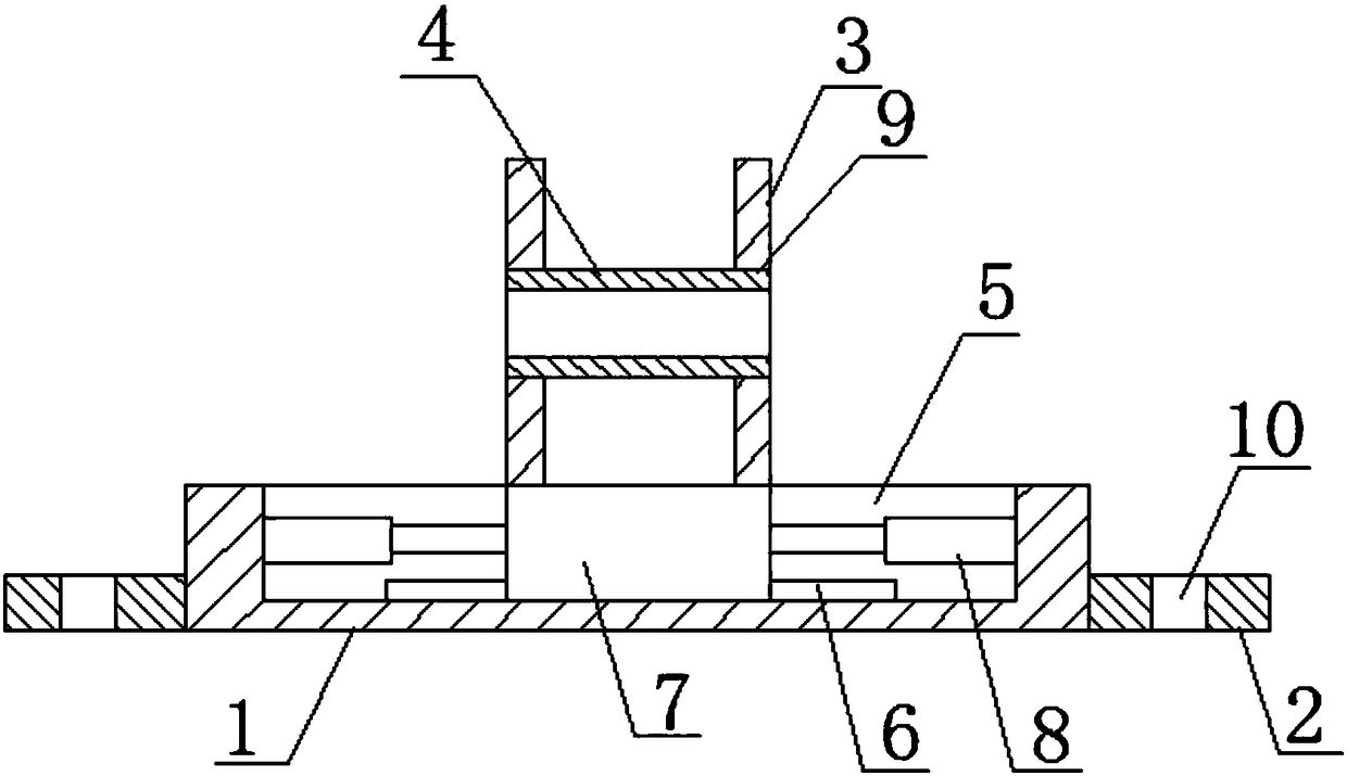
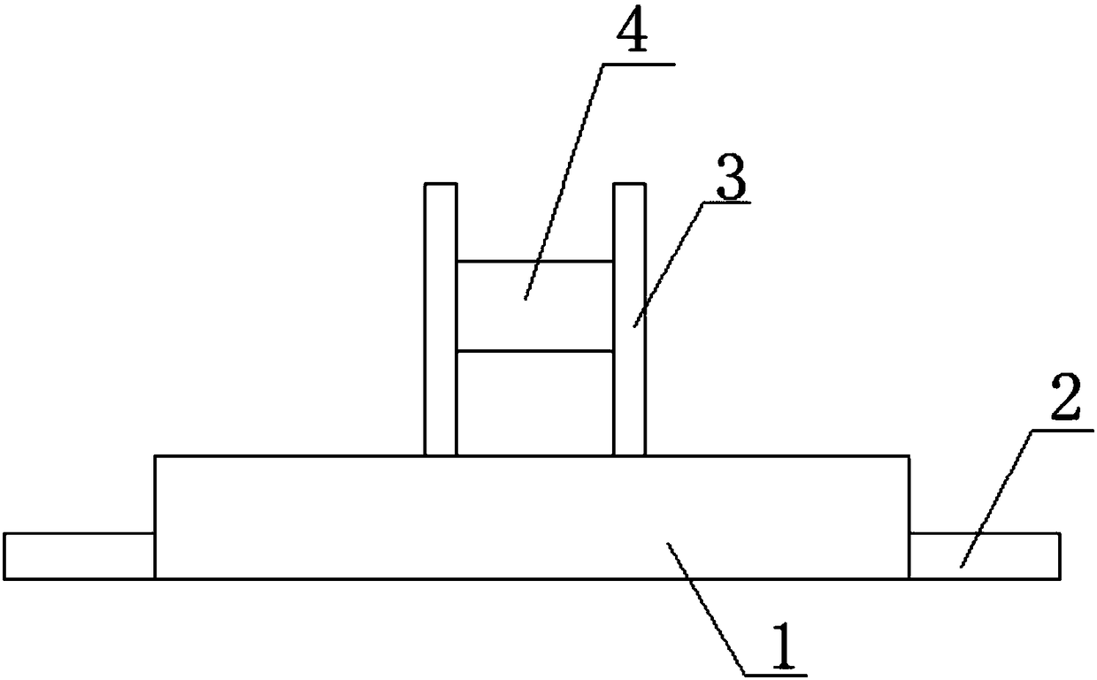
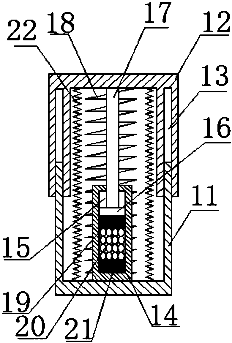
The invention discloses a damping type engine support which comprises an installing base. Installing plates are symmetrically arranged at the left end and the right end of the installing base. A damping cavity is formed in the upper side of the installing base. A sliding rail is arranged at the lower end in the damping cavity. The sliding rail is provided with a sliding base. Damping devices are arranged on the left side and the right side of the sliding base correspondingly. The outer ends of the damping devices are connected with the damping cavity. Supporting plates are arranged on the upper side of the sliding base in a bilateral symmetry manner. Fixing holes are formed in the supporting plates. The fixing holes are provided with fixing cylinders. Upper and lower magnets, damping springs and damping airbags are matched mutually, the better buffering effect on vibration generated by an engine is achieved, the space utilization rate of the engine will not be influenced, and assembling is facilitated.

Description

technical field [0001] The invention relates to the technical field of engine brackets, in particular to a shock-absorbing engine bracket. Background technique [0002] The engine bracket is an important stress-bearing part for the fixing of the automobile engine, and plays an important role in the fixed support of the engine. The engine is accompanied by different degrees of vibration during the working process. The engine bracket has been working in such a very harsh environment, so the engine and the engine bracket need to be fixed and stable; and the existing engine and the engine bracket Usually, a rubber sleeve is provided for shock absorption, but the connection between the engine and the engine bracket must be tightened during the installation process, which will inevitably cause deformation of the rubber sleeve, so the cushioning and shock absorption effect of the rubber sleeve is at the beginning of installation. It is reduced to a certain extent, and at the same ...

Claims


Application Information

Patent Timeline
Patent Type & Authority Applications(China)
IPC IPC(8): F16M1/04F16F15/023F16F15/03F16F15/04
CPCF16F15/0232F16F15/03F16F15/046F16M1/04
Inventor 王玉山范煜程玉成严建文时春生付冬生汪海明李岩
Owner ANHUI SIYUAN SANQING INTELLIGENT MFG CO LTD
Why Eureka
Try Eureka