Steel structure construction welding main beam monitoring device

A technology for monitoring devices and steel structures, applied to measuring devices, optical devices, instruments, etc., can solve problems such as inaccurate monitoring and danger

Active Publication Date: 2018-10-02
洛阳市鑫晟鑫建筑科技有限公司
View PDF6 Cites 5 Cited by
  • Summary
  • Abstract
  • Description
  • Claims
  • Application Information

AI Technical Summary

Problems solved by technology

[0004] In order to overcome the disadvantages that steel structures are usually monitored manually with the naked eye, but the monitoring is not accurate and can easily lead to dangers. Therefore, the technical problem of the prese

Method used


Image

  • Steel structure construction welding main beam monitoring device
  • Steel structure construction welding main beam monitoring device
  • Steel structure construction welding main beam monitoring device

Examples


Embodiment 1

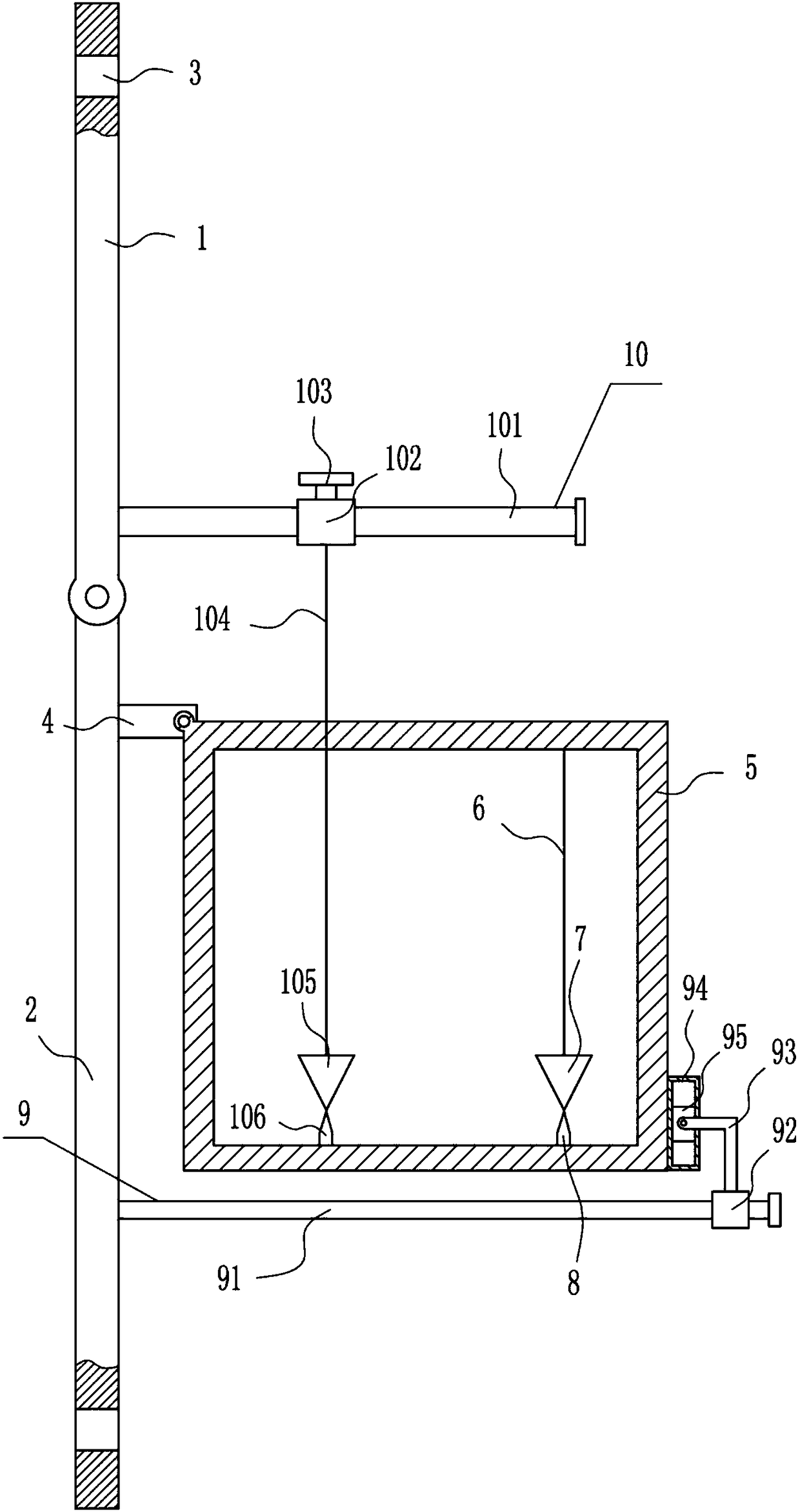
[0028] A steel structure building welding girder monitoring device, such as Figure 1-5 As shown, it includes a first mounting plate 1, a second mounting plate 2, a connecting block 4, a frame 5, a sling 6, a first tapered block 7, a first pointer 8, an adjusting device 9 and a monitoring device 10, the first The bottom of the mounting plate 1 is rotatably installed with a second mounting plate 2, the upper part of the first mounting plate 1 and the lower part of the second mounting plate 2 are provided with mounting holes 3, and the upper part of the right side of the second mounting plate 2 is equipped with a connecting block 4 , the right end of the connecting block 4 is rotatably installed with a frame 5 , the top right side of the frame 5 is connected with a suspension rope 6 , the tail end of the suspension rope 6 is equipped with a first tapered block 7 , and the bottom right side of the frame 5 is equipped with a first pointer 8. The first pointer 8 is located directly...

Embodiment 2

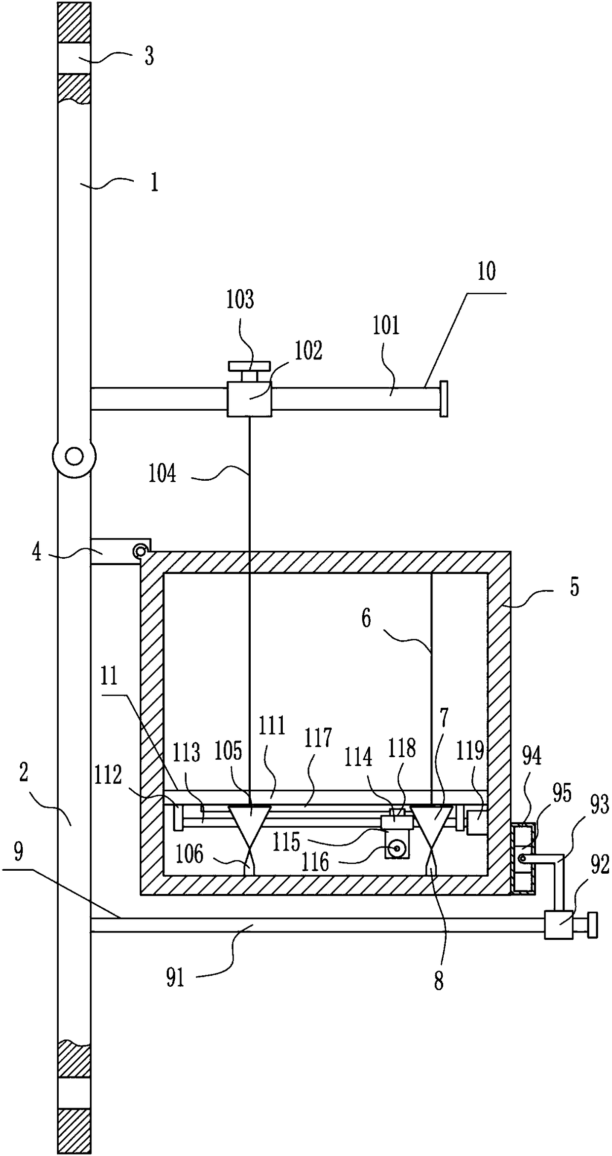
[0030] A steel structure building welding girder monitoring device, such as Figure 1-5 As shown, it includes a first mounting plate 1, a second mounting plate 2, a connecting block 4, a frame 5, a sling 6, a first tapered block 7, a first pointer 8, an adjusting device 9 and a monitoring device 10, the first The bottom of the mounting plate 1 is rotatably installed with a second mounting plate 2, the upper part of the first mounting plate 1 and the lower part of the second mounting plate 2 are provided with mounting holes 3, and the upper part of the right side of the second mounting plate 2 is equipped with a connecting block 4 , the right end of the connecting block 4 is rotatably installed with a frame 5 , the top right side of the frame 5 is connected with a suspension rope 6 , the tail end of the suspension rope 6 is equipped with a first tapered block 7 , and the bottom right side of the frame 5 is equipped with a first pointer 8. The first pointer 8 is located directly...

Embodiment 3

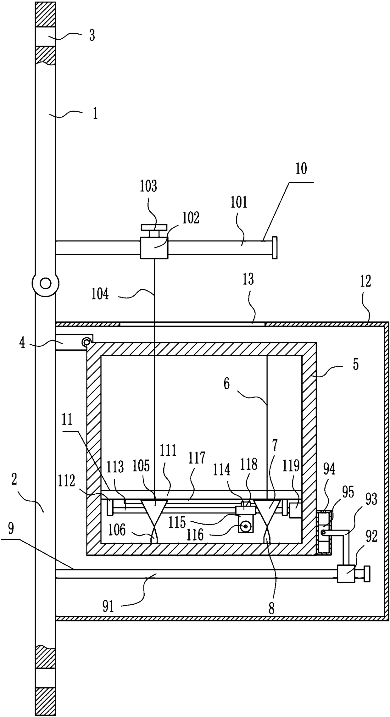
[0033] A steel structure building welding girder monitoring device, such as Figure 1-5 As shown, it includes a first mounting plate 1, a second mounting plate 2, a connecting block 4, a frame 5, a sling 6, a first tapered block 7, a first pointer 8, an adjusting device 9 and a monitoring device 10, the first The bottom of the mounting plate 1 is rotatably installed with a second mounting plate 2, the upper part of the first mounting plate 1 and the lower part of the second mounting plate 2 are provided with mounting holes 3, and the upper part of the right side of the second mounting plate 2 is equipped with a connecting block 4 , the right end of the connecting block 4 is rotatably installed with a frame 5 , the top right side of the frame 5 is connected with a suspension rope 6 , the tail end of the suspension rope 6 is equipped with a first tapered block 7 , and the bottom right side of the frame 5 is equipped with a first pointer 8. The first pointer 8 is located directly...


PUM


Abstract

The invention relates to a monitoring device, and particularly to a steel structure construction welding main beam monitoring device. Therefore the invention settles a technical problem of supplying the steel structure construction welding main beam monitoring device which does not require artificial direct monitoring to a steel structure, high monitoring accuracy and no easy danger. The steel structure construction welding main beam monitoring device is characterized in that the steel structure construction welding main beam monitoring device comprises a first mounting board, a second mounting board, etc.; the bottom end of the first mounting board is provided with the second mounting board which is rotatably mounted; the upper part of the first mounting board and the lower part of the second mounting board are provided with mounting holes; and the upper part of the right side surface of the second mounting board is provided with a connecting block. The steel structure construction welding main beam monitoring device can more accurately perform monitoring on the steel structure through the monitoring device; and through a viewing device, an operator can more conveniently view thepositions of a first conical block and a second conical block, thereby determining whether deformation of the steel structure occurs and realizing effects of high accuracy and no easy danger without artificial direct monitoring to the steel structure.

Description

technical field [0001] The invention relates to a monitoring device, in particular to a monitoring device for welding main girders of steel structure buildings. Background technique [0002] Buildings are structures built by people using all available materials such as soil, stone, wood, steel, glass, reeds, plastics, and ice. Architecture itself is not an end, the purpose of architecture is to obtain the "space" formed by architecture. It is an artificial environment created by people in order to meet the needs of social life, using the material and technological means they have mastered, and using certain scientific laws, feng shui concepts and aesthetic principles. [0003] After the welding of the steel structure is completed, in order to know whether the steel structure is deformed after long-term use, the steel structure will be monitored to prevent danger from occurring. Generally, the steel structure is watched and monitored manually with the naked eye, but the moni...

Claims


Application Information

Patent Timeline
IPC IPC(8): G01B11/16
CPCG01B11/16
Inventor 朱群成刘俊余胡舒绮
Owner 洛阳市鑫晟鑫建筑科技有限公司
Why Eureka
Try Eureka