Readout circuit

A technology for reading out circuits and current signals, applied in the field of readout circuits, can solve problems such as being unable to suppress, achieve accurate distance information, and reduce the effect of time identification errors

Inactive Publication Date: 2018-10-02
INFORMATION SCI RES INST OF CETC
View PDF6 Cites 5 Cited by
  • Summary
  • Abstract
  • Description
  • Claims
  • Application Information

AI Technical Summary

Problems solved by technology

The constant ratio timing identification method effectively eliminates the error caused by the chang...

Method used


Image

  • Readout circuit
  • Readout circuit
  • Readout circuit

Examples


Embodiment Construction

[0016] The specific implementation manners of the present invention will be further described in detail below in conjunction with the accompanying drawings and embodiments. The following examples are used to illustrate the present invention, but are not intended to limit the scope of the present invention.

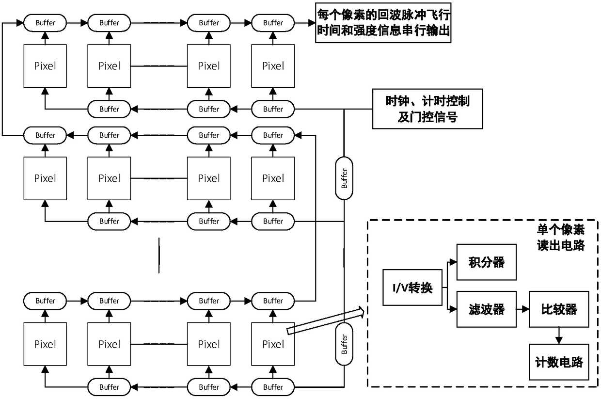
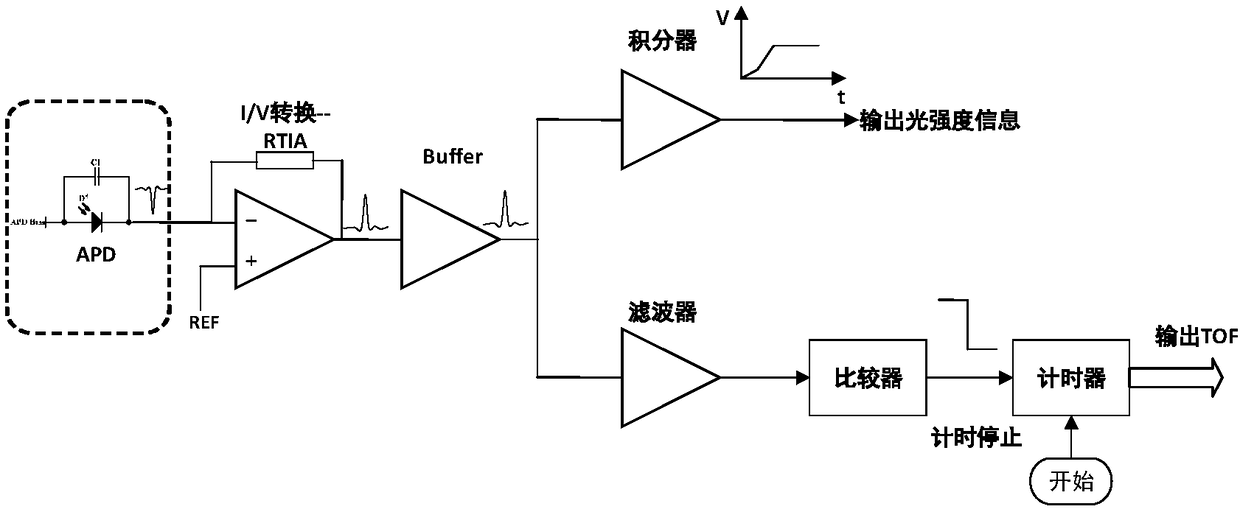
[0017] The overall framework of the readout circuit of this scheme is a linear APD focal plane readout circuit. The function of the readout circuit is to read the echo pulse flight time and intensity information measured by the APD of each pixel in the focal plane detector to complete "four-dimensional" imaging . Each pixel in the APD array corresponds to a readout circuit, which includes I / V conversion, integrator, filter and timer, which will be described in detail in the next subsection. The time-of-flight and light intensity information output by each pixel is sequentially read through the serial link. In the data readout, the buffer register is multiplexed, and the d...


PUM


Abstract

The invention provides a readout circuit. The readout circuit is configured to read out a current signal outputted by an avalanche diode operating in a linear mode according to a certain frame rate toprovide a stopping criterion for a follow-up timing circuit; and thus flight time and an echo light intensity of the pulse are obtained to complete the function of laser detection. According to the readout circuit, a stopping time of a timer is obtained based on a signal received by an APD, so that a time discrimination error is reduced as much as possible and thus accurate flight time TOF is calculated and precise distance information is obtained.

Description

technical field [0001] The invention relates to the field of signal processing in laser three-dimensional imaging, in particular to a readout circuit. Background technique [0002] Laser 3D imaging is a typical application of lidar. In general, a range image (angle-angle-distance) is called a three-dimensional image. There are many kinds of optical three-dimensional acquisition techniques, and the pulse time-of-flight method is widely used. By sampling the pixel division of the target surface outline, the angle-angle-distance information of each pixel is obtained to determine its spatial position, and the point cloud formed by the combination of all measured pixels can describe the target outline. . [0003] The pulse time-of-flight method (TOF, time offlight) is to obtain the distance of the pixel by measuring the time-of-flight of a single light pulse. After the light pulse is sent, it is reflected on the target surface, and then the echo light signal is detected by th...

Claims


Application Information

Patent Timeline
IPC IPC(8): G01S7/486
CPCG01S7/4861
Inventor 刘大川刘杰胡小燕
Owner INFORMATION SCI RES INST OF CETC
Why Eureka
Try Eureka