
Laser signal processing chip and laser radar system

A laser signal and lidar technology, applied in the field of microelectronics, can solve problems such as reducing the detection performance of the lidar system

Pending Publication Date: 2017-12-26
北京佳光科技有限公司
View PDF0 Cites 5 Cited by
  • Summary
  • Abstract
  • Description
  • Claims
  • Application Information

AI Technical Summary

Problems solved by technology

[0004] In view of this, the object of the present invention is to provide a laser signal processing chip and a laser radar system, which are used to solve the problems in the prior art that the detection performance of the laser radar system is reduced due to the cascading of multiple chips

Method used


Image

  • Laser signal processing chip and laser radar system
  • Laser signal processing chip and laser radar system
  • Laser signal processing chip and laser radar system

Examples


Embodiment Construction

[0031] In order to make the purpose, technical solutions and advantages of the embodiments of the present invention clearer, the technical solutions in the embodiments of the present invention will be clearly and completely described below in conjunction with the drawings in the embodiments of the present invention. Obviously, the described embodiments are only It is a part of embodiments of the present invention, but not all embodiments. The components of the embodiments of the invention generally described and illustrated in the figures herein may be arranged and designed in a variety of different configurations. Accordingly, the following detailed description of the embodiments of the invention provided in the accompanying drawings is not intended to limit the scope of the claimed invention, but merely represents selected embodiments of the invention. Based on the embodiments of the present invention, all other embodiments obtained by those skilled in the art without making...


PUM


Abstract

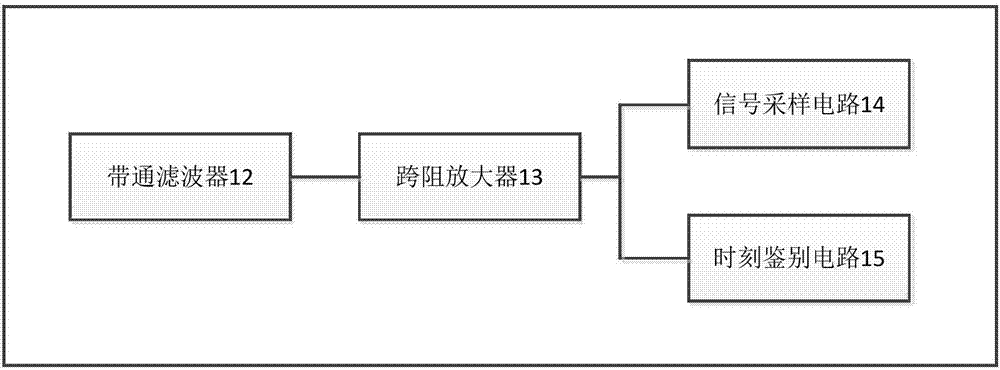
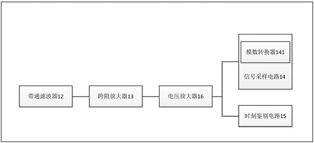
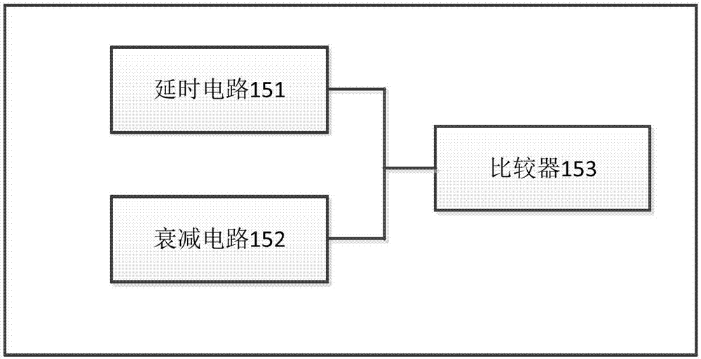
The invention provides a laser signal processing chip and a laser radar system. The chip comprises a band-pass filter, a trans-impedance amplifier, a signal sampling circuit and a time discrimination circuit, the band-pass filter is used for filtering received return wave current signals according to the set frequency to obtain filter current signals, and the filter current signals are transmitted to the trans-impedance amplifier; the return wave current signals are generated when received laser signals reflected by objects to the detected are converted by an optical-to-electrical transducer in the laser radar system; the trans-impedance amplifier is used for converting the received filter current signals to return wave voltage signals, and the wave voltage signals are transmitted to the signal sampling circuit and the time discrimination circuit respectively; the signal sampling circuit is used for sampling the received return wave voltage signals, and gray level information is obtained; the time discrimination circuit is used for processing the received return wave voltage signals respectively, and receiving time of the laser signals is obtained.

Description

technical field [0001] The invention relates to the technical field of microelectronics, in particular to a laser signal processing chip and a laser radar system. Background technique [0002] In a traditional laser radar system, the laser receiving front-end is generally composed of discrete chips, and each chip performs processing on the received laser signal, such as signal filtering, signal multi-stage amplification, time identification, and peak sampling. The core key part of the radar system is directly related to the performance of the overall radar system. [0003] Since the chip in the existing lidar system contains many functional modules, and the echo signal of the lidar is extremely weak, it is very susceptible to crosstalk from other signals, and noise will affect the signal quality. At the same time, the board-level design of discrete devices leads to increased system complexity, poor stability, and high power consumption, which greatly limits the continuous i...

Claims


Application Information

Patent Timeline
Patent Type & Authority Applications(China)
IPC IPC(8): G01S7/486G01S7/491G01S17/02
CPCG01S7/486G01S7/4861G01S7/4912G01S7/4913G01S17/02
Inventor 王豪刘小康
Owner 北京佳光科技有限公司
Learn More