
Baking oven and photoresist pre-baking method

A baking furnace and baking cavity technology, applied in optics, optomechanical equipment, instruments, etc., can solve the problems of uneven substrate photoresist film thickness, uneven heating, uneven photoresist film thickness, etc., to avoid photoresist Non-uniform film thickness and line width, and the effect of improving quality

Inactive Publication Date: 2018-10-02
SHENZHEN CHINA STAR OPTOELECTRONICS TECH CO LTD
View PDF5 Cites 0 Cited by
  • Summary
  • Abstract
  • Description
  • Claims
  • Application Information

AI Technical Summary

Problems solved by technology

[0006] 1) The room temperature airflow outside the cavity enters the high temperature cavity, which disturbs the uniformity of the temperature of the hot plate, which causes the local temperature of the hot plate to be temporarily uneven;
[0007] 2) The uneven temperature of the hot plate will affect the uneven heating of the glass substrate when it is baked by the hot plate, resulting in different volatilization rates of the photoresist solvent in the surface, and finally resulting in uneven thickness of the photoresist film on the substrate;
[0008] 3) The uneven temperature of the hot plate will affect the difference in the curing degree of the photoresist on the surface of the glass substrate, which will eventually lead to the difference in the line width dimension (CD) of the photoresist pattern after development
[0009] However, the uneven film thickness and line width of the photoresist will eventually affect the quality of the product

Method used


Image

  • Baking oven and photoresist pre-baking method
  • Baking oven and photoresist pre-baking method
  • Baking oven and photoresist pre-baking method

Examples


Embodiment Construction

[0049] In order to further illustrate the technical means adopted by the present invention and its effects, the following describes in detail in conjunction with preferred embodiments of the present invention and accompanying drawings.

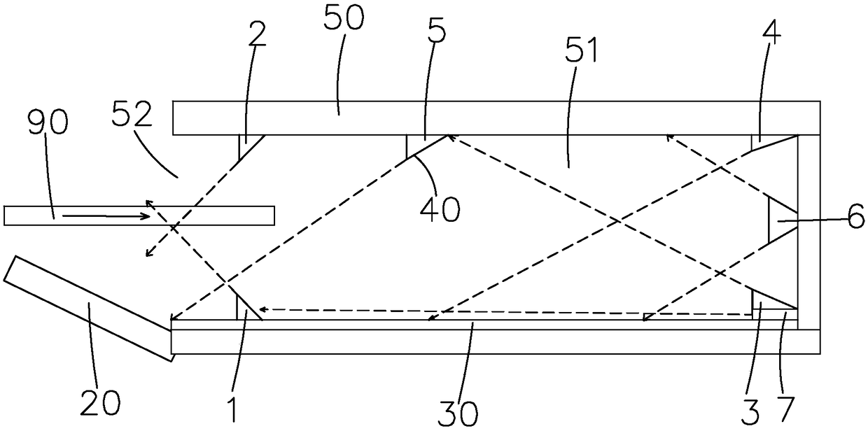
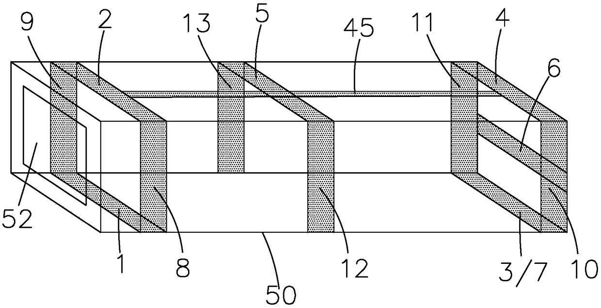
[0050] see figure 1 , the present invention firstly provides a kind of oven, comprises:

[0051] A furnace body 50, the inside of which is a baking cavity 51, and one side of the furnace body 50 is provided with an entrance and exit 52;

[0052] The switch door 20 is installed at the entrance and exit 52 of the furnace body 50;

[0053] The heating plate 30 is arranged at the bottom of the baking cavity 51 and is used to heat the substrate 90;

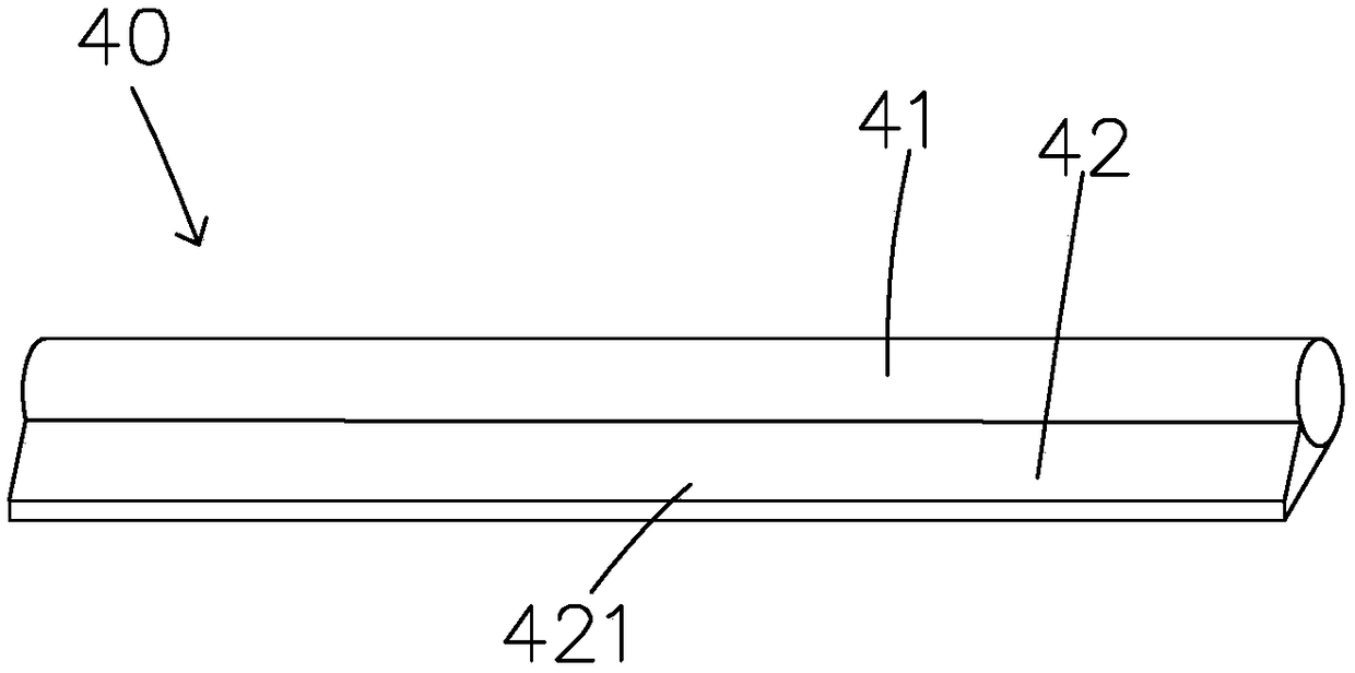
[0054] A plurality of jet pipes 40 are arranged in the baking cavity 51;

[0055] When the switch door 20 is opened, the plurality of gas injection pipes 40 are used to spray hot gas to the inlet and outlet 52 to prevent the gas outside the baking cavity 51 from entering;

[0056] Such as image 3...


PUM


Abstract

The invention provides a baking oven and a photoresist pre-baking method. The baking oven provided by the invention comprises an oven body, a switching door, a heating plate and a plurality of air injection pipes; when the switching door is open, the air injection pipes are used for injecting hot air into inlets and outlets so as to prevent gas outside a baking cavity from entering, an airflow outside the baking cavity can be effectively prevented from influencing the temperature of the heating plate at the position of the switching door, photoresist film thickness non-uniformity and line width non-uniformity in the pre-baking process caused by temperature non-uniformity at the position of the switching door are avoided, and then the quality of a display product is effectively improved. According to the photoresist pre-baking method provided by the invention, photoresist pre-baking is carried out by using the baking oven, the airflow outside the baking oven can be effectively preventedfrom influencing the temperature of the hating plate at the position of the switching door, photoresist film thickness non-uniformity and line width non-uniformity in the pre-baking process caused bytemperature non-uniformity at the position of the switching door are avoided, and then the quality of the display product is effectively improved.

Description

technical field [0001] The invention relates to the technical field of display manufacture, in particular to a baking oven and a photoresist pre-baking method. Background technique [0002] In the field of display technology, flat-panel displays such as Liquid Crystal Display (LCD) and Organic Light Emitting Diode (OLED) displays have gradually replaced CRT displays, and are widely used in LCD TVs, mobile phones, personal digital assistants, digital Cameras, computer or laptop screens, etc. [0003] The display panel is an important part of LCD and OLED. Whether it is an LCD display panel or an OLED display panel, it usually has a thin film transistor (Thin Film Transistor, TFT) substrate. Taking the LCD display panel as an example, it is mainly composed of a TFT substrate, a color filter (CF) substrate, a liquid crystal layer and a sealant (Sealant) arranged between the two substrates, and its molding process generally includes: the front section Array (Array) process (t...

Claims


Application Information

Patent Timeline
IPC IPC(8): G03F7/16
CPCG03F7/168
Inventor 涂乐志
Owner SHENZHEN CHINA STAR OPTOELECTRONICS TECH CO LTD
Learn More