Cutting tool, particularly boring bar and method for machining a plurality of bores

A technology of cutting tools and boring bars, which is applied in the field of boring bars and multiple holes, and can solve difficult problems

Active Publication Date: 2018-10-09
KENNAMETAL INC
View PDF8 Cites 0 Cited by
  • Summary
  • Abstract
  • Description
  • Claims
  • Application Information

AI Technical Summary

Problems solved by technology

As is known, for example, for reamers, the direct support of the boring bar in the region of the respective cutting edge by the guid...

Method used


Image

  • Cutting tool, particularly boring bar and method for machining a plurality of bores
  • Cutting tool, particularly boring bar and method for machining a plurality of bores
  • Cutting tool, particularly boring bar and method for machining a plurality of bores

Examples


Embodiment Construction

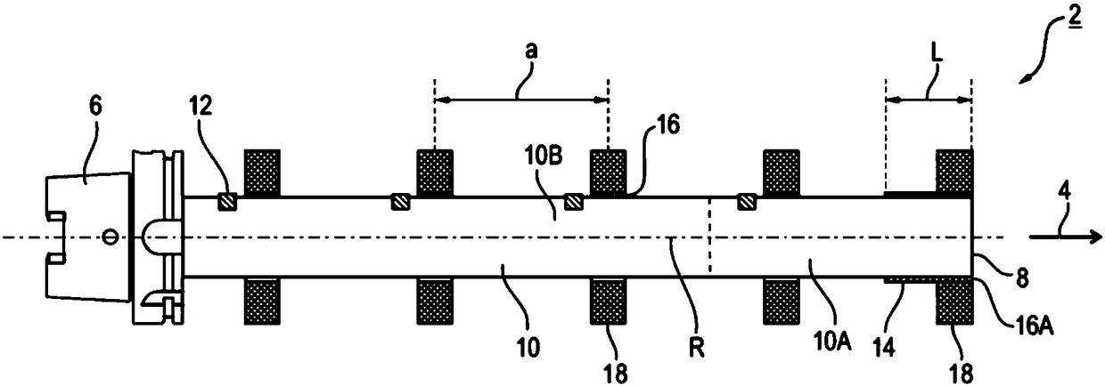
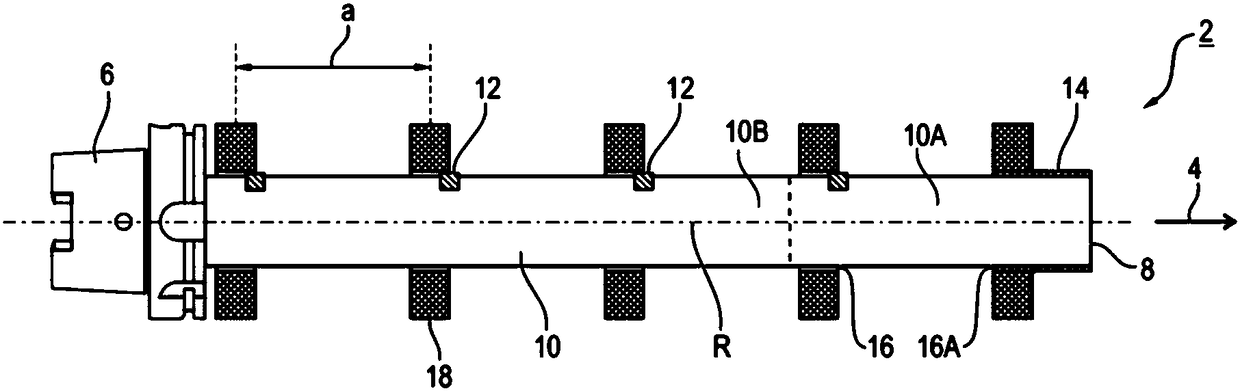
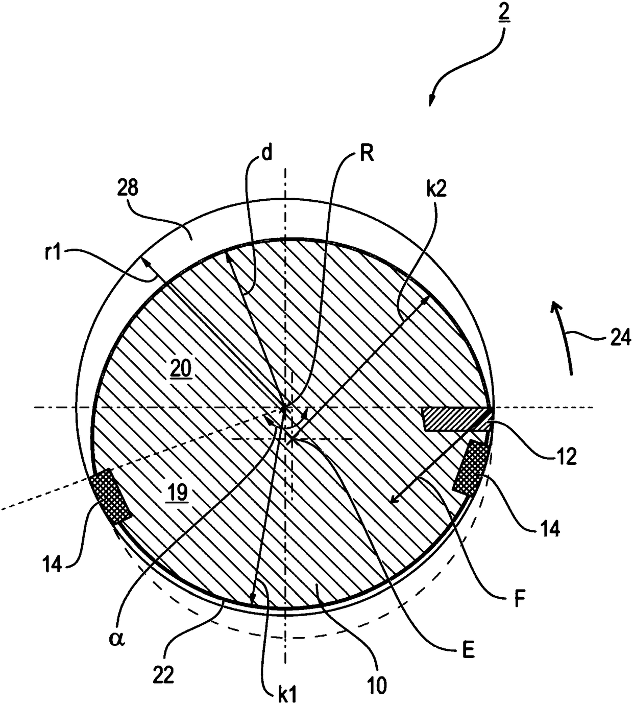
[0059] According to available from Figure 1A , 1B or Figure 5A , 5B, the two implementation variants derived from 5C, the boring bar 2 also configured as a tandem boring bar extends in the axial direction 4 from the rear adapter 6 to the front end side 8 . The boring bar 2 next to the adapter 6 has a rod-shaped base body 10 , on which cutting elements 12 spaced apart from one another in the axial direction are fastened in respective working positions on the base body 10 . All cutting elements 12 are arranged here on the base body 10 at the same angular position and thus lie on a line. Only one cutting element 12 is arranged on the base body 10 for each working position. Furthermore, a guide element 14 designed in the form of a guide plate is arranged on the base body at the guide point of the base body 10 . The cutting element 12 as well as the guide element 14 form a functional element.

[0060] As an alternative to the illustrated solution in which the cutting elements...


PUM


Abstract

The present application relates to a cutting tool, in particular a boring bar, and a method for machining a plurality of bores. The cutting tool comprises has a basic body that extends in an axial direction and having an axis of rotation, a cutting element, as well as a number of guide elements. The guide elements, relative to the axis of rotation, separate a guide radius. The basic body, viewed in a cross-section, is divided into a functional region and an eccentric region. The cutting element and the guide elements are distributed around the circumference of the basic body in an angular range less than 180 degree. The circumferential side of the basic body has a distance to the axis of rotation in the eccentric region that is less in comparison with the guide radius. Furthermore, the basic body has a base body as well as at least one balance element that is positioned within the eccentric region and is designed to at least partially balance an otherwise existing imbalance. A partingplane is formed between the base body and the balance element and is oriented substantially parallel to a midplane that is defined by the axis of rotation and the cutting edge of the cutting element.

Description

technical field [0001] The invention relates to a rotary cutting tool, in particular a boring bar, having the features according to the preamble of patent claim 1, and to a tool for machining with the aid of such a cutting tool, especially spaced apart from each other in the axial direction. Multiple orifice approach with preset pitch dimensions. Background technique [0002] Such a boring bar and such a method are described, for example, in WO 2014 / 195007 A1. [0003] Bearing shafts, such as camshafts or crankshafts in motor vehicles, are usually supported in bearing bores, hereinafter referred to simply as bores, on a plurality of axially spaced bearing beams. Here, the individual bores are usually reamed to final size by means of so-called tandem boring bars. The tandem boring bar has cutting edges arranged offset from each other by a pitch dimension in the axial direction, which cutting edges are respectively provided for machining a respective bore, so that by means o...

Claims


Application Information

Patent Timeline
IPC IPC(8): B23B29/02B23B35/00
CPCB23B29/022B23B41/12B23B29/02B23B35/00B23B27/002B23B2229/04B23B2229/08B23B2250/04B23B51/0054
Inventor M.哈克S.昆希尔
Owner KENNAMETAL INC
Why Eureka
Try Eureka