Mechanical-arm- assisted vertical supercharged air-cushion icebreaker

A technology for mechanical arms and icebreakers, applied in the field of vertically pressurized air-cushion icebreakers, which can solve the problems of inconvenient disassembly of mechanical arms, unfavorable energy conservation and environmental protection, and high energy consumption, and achieve the effects of simple structure, environmental protection, and energy consumption reduction

Inactive Publication Date: 2018-10-09
付志伟
View PDF5 Cites 6 Cited by
  • Summary
  • Abstract
  • Description
  • Claims
  • Application Information

AI Technical Summary

Problems solved by technology

[0002] The vertically pressurized air-cushion icebreaker is a hull that can inflate itself quickly. It can not only transport goods quickly and maneuver on the ice, but also break through thicker ice layers. It can provide equipment support for operations in cold regions. , The traditional icebreaker mainly relies on its own power to smash the ice layer, which is slow, inefficient, and consumes a lot of energy. The vertically pressurized air cushion icebreaker has the characteristics of maneuverability and high-speed driving on the ice surface, and is a very important icebreaking equipment. , basically have ice-breaking mechanical arms, but the current design of the vertically pressurized air-cushion icebreaker still has shortcomings. In some cold regions, it is summer, and after the ice melts, it is not easy to disassemble the mechanical arm and restore it to an ordinary hovercraft for shipping. Excessive energy consumption is not conducive to energy saving and environmental protection. Therefore, we propose a vertically pressurized air-cushion icebreaker assisted by a mechanical arm to solve the above problems.

Method used


Image

  • Mechanical-arm- assisted vertical supercharged air-cushion icebreaker
  • Mechanical-arm- assisted vertical supercharged air-cushion icebreaker
  • Mechanical-arm- assisted vertical supercharged air-cushion icebreaker

Examples


Embodiment Construction

[0019] The following will clearly and completely describe the technical solutions in the embodiments of the present invention with reference to the accompanying drawings in the embodiments of the present invention. Obviously, the described embodiments are only some, not all, embodiments of the present invention.

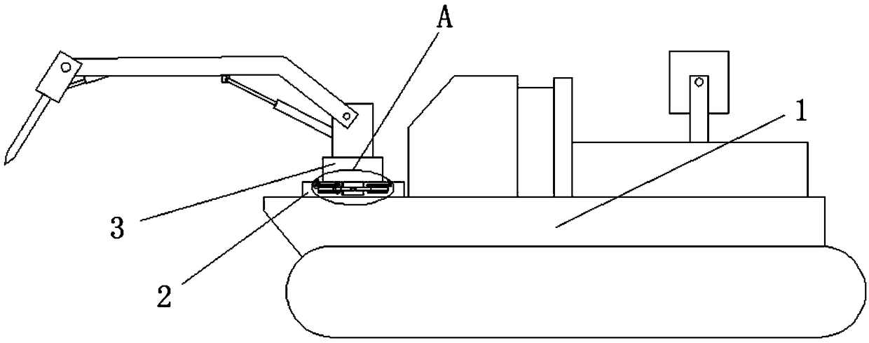
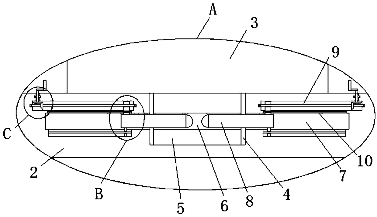
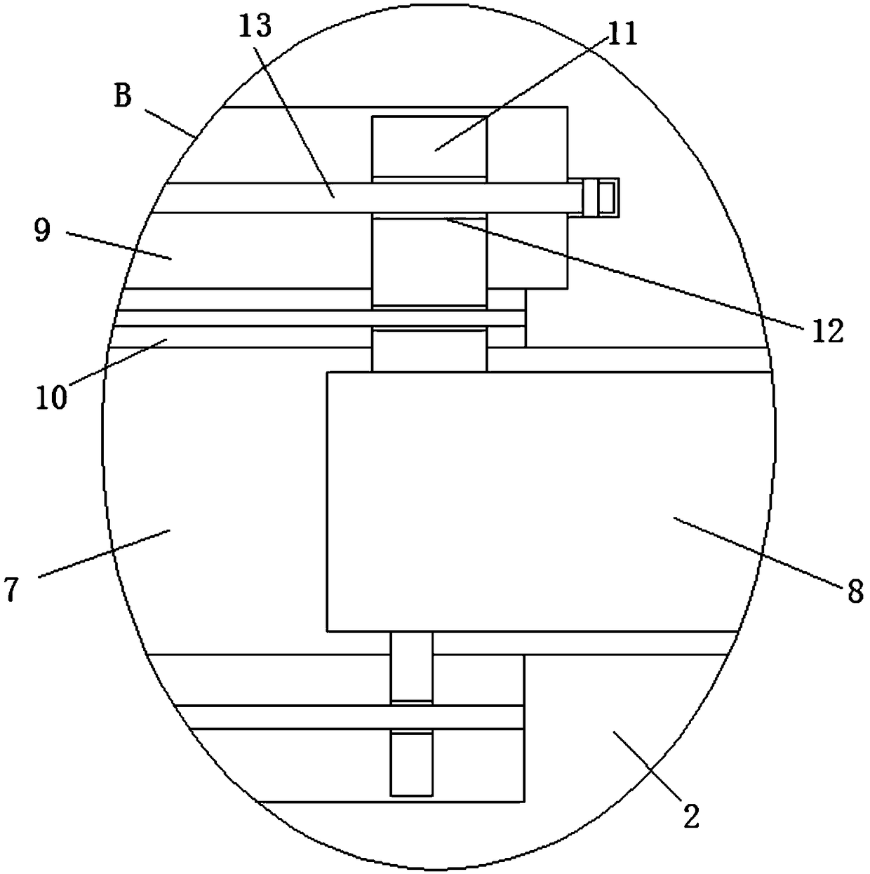
[0020] refer to Figure 1-4 , a vertical pressurized air cushion icebreaker assisted by a mechanical arm, comprising a hovercraft body 1, a fixed block 2 is fixedly installed on the hovercraft body 1, an icebreaking mechanical arm body 3 is arranged on the top of the fixed block 2, and an icebreaker arm body 3 is arranged on the top of the fixed block 2. There is a first groove 4, a first pin shaft 5 is slidably installed in the first groove 4, a first through hole 6 is provided on the first pin shaft 5, and a first through hole 6 is provided on the inner walls of both sides of the first groove 4. Two grooves 7, a second pin shaft 8 is slidably installed in the secon...


PUM


Abstract

The invention discloses a mechanical-arm-assisted vertical supercharged air-cushion icebreaker. The mechanical-arm-assisted vertical supercharged air-cushion icebreaker comprises an air cushion ship body. The air cushion ship body is fixedly provided with a fixed block, an ice-breaking mechanical arm body is arranged at the top of the fixed block, a first groove is formed in the top of the fixed block, a first pin shaft is slidably installed in the first groove, and a first through hole is formed in the first pin shaft. Second grooves are formed in the inner walls of the two sides of the firstgroove, and second pin shafts are slidably installed in the second grooves. The ends, close to each other, of the two second pin shafts extend into the first through hole. The second pin shafts are slidably connected to the inner wall of the first through hole, and two chambers are formed in the fixed block. The structure is simple, the operation is convenient, a mechanical arm can be quickly disassembled by simple rotational action, therefore people can conveniently use the air cushion ship body for shipping in the absence of ice in summer, energy consumption is reduced, and the mechanical-arm-assisted vertical supercharged air-cushion icebreaker is beneficial to saving cost and protecting the environment.

Description

technical field [0001] The invention relates to the technical field of air-cushion icebreakers, in particular to a vertical pressurized air-cushion icebreaker assisted by a mechanical arm. Background technique [0002] The vertically pressurized air-cushion icebreaker is a hull that can inflate itself quickly. It can not only transport goods quickly and maneuver on the ice, but also break through thicker ice layers. It can provide equipment support for operations in cold regions. , The traditional icebreaker mainly relies on its own power to smash the ice layer, which is slow, inefficient, and consumes a lot of energy. The vertically pressurized air cushion icebreaker has the characteristics of maneuverability and high-speed driving on the ice surface, and is a very important icebreaking equipment. , basically have ice-breaking mechanical arms, but the current design of the vertically pressurized air-cushion icebreaker still has shortcomings. In some cold regions, it is summ...

Claims


Application Information

Patent Timeline
Patent Type & Authority Applications(China)
IPC IPC(8): B63B35/08B60V3/06
CPCB60V3/06B63B35/083
Inventor 付志伟
Owner 付志伟
Why Eureka
Try Eureka