
Rotary powder scraping device

A rotary and rotating shaft technology, which is applied in the separation of dispersed particles, chemical instruments and methods, and filtration of dispersed particles, can solve the problems of inability to rotate powder scraping, scratches on the wall, troublesome decoration work, etc., to avoid splashing , avoid scratches, facilitate the effect of speed and size

Inactive Publication Date: 2018-10-09
广州元坤新材料有限公司
View PDF0 Cites 0 Cited by
  • Summary
  • Abstract
  • Description
  • Claims
  • Application Information

AI Technical Summary

Problems solved by technology

[0002] Now with the continuous advancement of science and technology, we pay more and more attention to the decoration of the interior of the house, so that we can live better. During the decoration process, we need to scrape off the dust on the surface of the wall, so as to facilitate the decoration of the wall later. Therefore, it is necessary to use a powder scraping device to scrape the powder on the wall. Although there are various types of powder scraping devices on the market, there are still some shortcomings. For powder scraping, the powder scraping is not complete, and the powder scraping cannot be done by rotation. Scraping the wall with a blade will easily leave scratches on the wall, which will cause trouble for the later decoration work. There will be a lot of dust in the process, so we propose a rotary powder scraping device for decoration with dust suction function, which can solve the above problems very well

Method used


Image

  • Rotary powder scraping device
  • Rotary powder scraping device
  • Rotary powder scraping device

Examples


Embodiment Construction

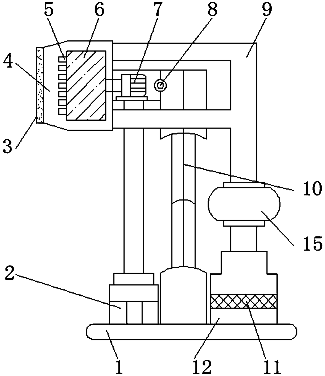
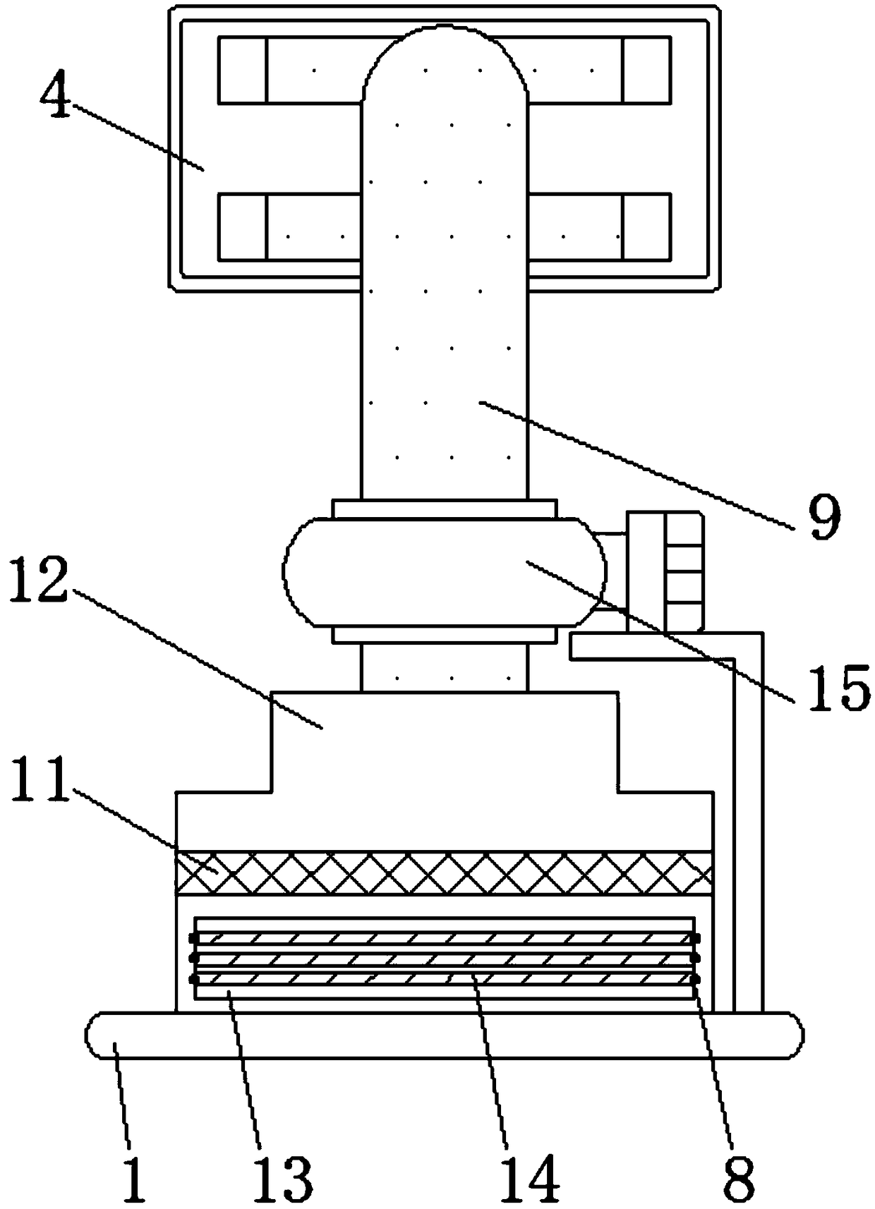
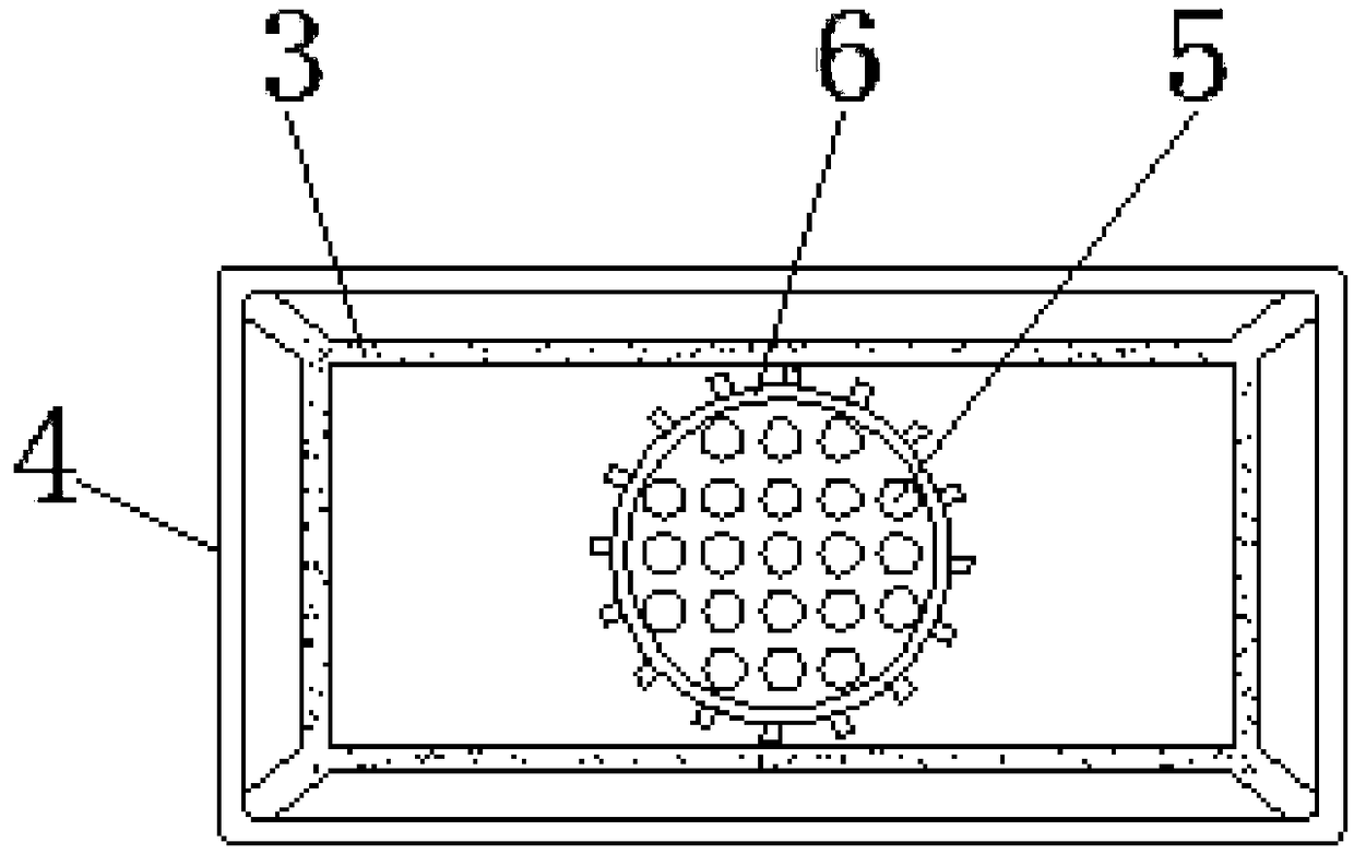
[0016] Such as Figure 1-Figure 3 As shown, a rotary powder scraping device mainly includes a base plate 1, a hydraulic cylinder 2, a suction piece 3, a protective cover 4, a scraper block 5, a fixed plate 6, a motor 7, a rotating shaft 8, a suction pipe 9, and a support rod 10 , Horizontal plate 11, dust collection chamber 12, through groove 13, support plate 14 and blower fan 15.

[0017] A hydraulic cylinder 2 is arranged on the upper left side of the bottom plate 1, and a suction piece 3 is installed above the hydraulic cylinder 2, and a protective cover 4 is fixed on the right side of the suction piece 3, and a scraper 5 is arranged inside the protective cover 4, and the protective cover The side section of 4 is trapezoidal, and the protective cover 4 is a telescopic structure, and the protective cover 4 and the suction piece 3 are integrally structured. The side section of the protective cover 4 is trapezoidal, which can well avoid the splashing of impurities, so that th...


PUM


Abstract

The invention relates to a rotary powder scraping device. The rotary powder scraping device mainly comprises a bottom plate and an air suction pipe, a hydraulic cylinder is arranged on the left side of the upper part of the bottom plate, and a suction piece is arranged above the hydraulic cylinder. A protective cover is fixed to the right side of the suction piece. The protective cover is internally provided with a scraping block. A fixing plate is mounted on the right side of the scraping block. A motor is fixed to the right side of the fixing plate. A rotating shaft is arranged on the rightside of the motor. A support rod is arranged on the right side of the rotating shaft. The protective cover is fixed to the left side of the air suction pipe. A draught fan is disposed under the air suction pipe. A powder collecting chamber is installed under the draught fan. A horizontal plate is fixed inside the powder collecting chamber. By arranging the protective cover, the protective cover isin a trapezoid shape by a side section view, and the scraped powder can be collected well; and at the same time, the protective cover and a wall are fixedly connected through the suction piece on theouter side of the protective cover, and therefore the powder is prevented from falling.

Description

technical field [0001] The invention relates to the technical field of powder scraping devices, in particular to a rotary powder scraping device. Background technique [0002] Now with the continuous advancement of science and technology, we pay more and more attention to the decoration of the interior of the house, so that we can live better. During the decoration process, we need to scrape off the dust on the surface of the wall, so as to facilitate the decoration of the wall later. Therefore, it is necessary to use a powder scraping device to scrape the powder on the wall. Although there are various types of powder scraping devices on the market, there are still some shortcomings. For powder scraping, the powder scraping is not complete, and the powder scraping cannot be done by rotation. Scraping the wall with a blade will easily leave scratches on the wall, which will cause trouble for the later decoration work. A large amount of dust will be generated during the proce...

Claims


Application Information

Patent Timeline
Patent Type & Authority Applications(China)
IPC IPC(8): E04F21/00B01D46/10
CPCB01D46/10E04F21/00
Inventor 笪利军李燕梅
Owner 广州元坤新材料有限公司
Learn More