Automobile cooling device with centrifugal fan structure and application method

A centrifugal fan and automobile cooling technology, which is applied in the cooling of engines, engine components, machines/engines, etc., can solve the problems of blockage of various components of the cooling device, inconvenient replacement and disassembly, and difficult cleaning, etc., and achieves convenient installation and simple structure. , the effect of solid structure

Pending Publication Date: 2018-10-09
泰铂(上海)环保科技股份有限公司
View PDF8 Cites 0 Cited by
  • Summary
  • Abstract
  • Description
  • Claims
  • Application Information

AI Technical Summary

Problems solved by technology

[0002] When the car is running, the cooling device installed on the windward side of the car is easily affected by the use environment. Not only the surface is dirty, but also it is easy to cause blockage of various parts of the cooling device, which needs to be cleaned regularly
At present, the purpose of dust prevention can be achieved by installing a dust-proof net on the surface of the cooling device, but after a period of use, the dust-proof net needs to be cleaned or replaced regularly, and there are problems such as inconvenient replacement and disassembly, and difficult cleaning

Method used


Image

  • Automobile cooling device with centrifugal fan structure and application method
  • Automobile cooling device with centrifugal fan structure and application method

Examples


Embodiment 1

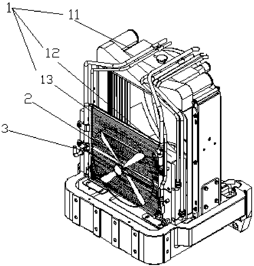
[0029] This embodiment provides a car cooling device with a centrifugal fan structure, its structure is detailed in the attached figure 1 , 2 As shown, it includes: a cooling device body 1 , a centrifugal fan 2 and a mounting frame 3 ; wherein, the centrifugal fan 2 is connected to the cooling device body 1 through the mounting frame 3 .

[0030] Further, the cooling device body 1 includes an engine radiator 11 , an oil cooler 12 and a condenser 13 , and the centrifugal fan 2 is arranged on the windward side of the condenser 13 through the installation frame 3 .

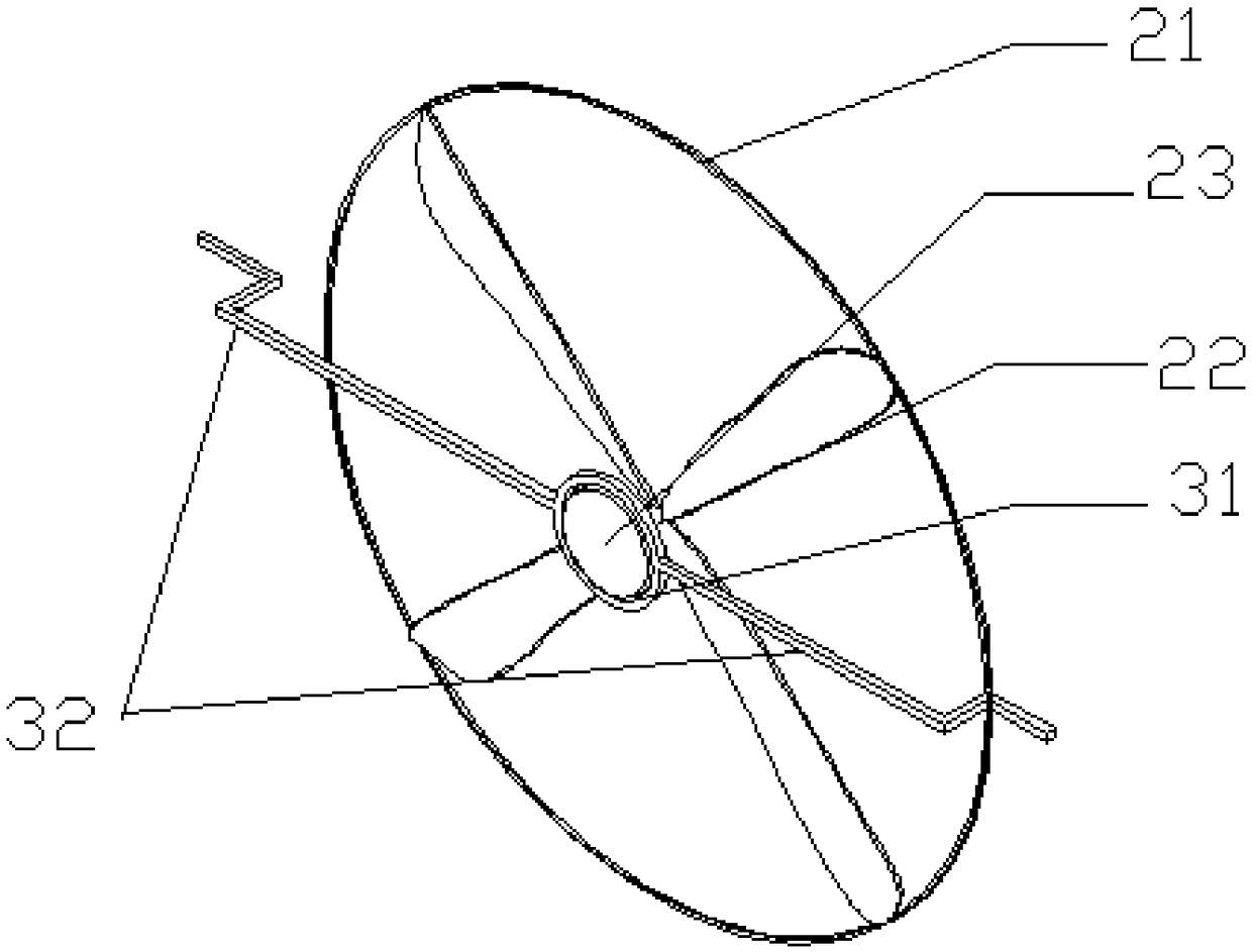
[0031] Further, the centrifugal fan 2 includes a net cover 21, an impeller 22, and a connecting shaft sleeve 23. The net cover 21 is divided into two parts, a front net cover and a rear net cover, and the front net cover and the rear net cover form an accommodation space; the impeller 22 It is arranged in the accommodating space; the front net cover, the impeller 22 and the rear net cover are sleeved on the connecti...

Embodiment 2

[0039] This embodiment provides an automobile cooling device with a centrifugal fan structure, and the device is the same as Embodiment 1.

[0040] This embodiment relates to a method of using an automobile cooling device with a centrifugal fan structure. When the automobile is running, the cooling device operates, and the wind generated by the engine radiator or the headwind wind drives the impeller to rotate. The rotation keeps the oncoming small particles of dust or sundries away from the cooling device; the centrifugal fan rotates counterclockwise.

[0041] In summary, the above embodiments 1-2 have the following effects:

[0042] (1) A centrifugal fan structure is installed on the windward side of the condenser of the cooling device body. The centrifugal fan drives itself to rotate through the wind generated by the wind or the radiator fan. The high-speed rotation makes the oncoming small particles of dust, particulate matter or Other sundries are not adsorbed in the hea...


PUM


Abstract

The invention provides an automobile cooling device with a centrifugal fan structure. The automobile cooling device comprises a cooling device body, a centrifugal fan and a mounting rack. The centrifugal fan is connected with the cooling device body through the mounting rack. The invention further discloses an application method of the automobile cooling device with the centrifugal fan structure.By means of high-speed rotation of the centrifugal fan, oncoming small-particle dust or particulate matter or other sundries cannot be adsorbed into various heat exchanger fins of the cooling device,the particulate matter and the sundries are effectively stopped, the function similar to a dustproof net is achieved, the centrifugal fan can operate without power dissipation, and environment protection and energy saving are achieved.

Description

technical field [0001] The invention relates to the field of automobile cooling devices, in particular to an automobile cooling device with a centrifugal fan structure and a usage method. Background technique [0002] When the car is running, the cooling device installed on the windward side of the front of the car is easily affected by the use environment. Not only the surface is dirty, but also it is easy to cause blockage of the components of the cooling device, which needs to be cleaned regularly. At present, the purpose of dust prevention can be achieved by installing a dust-proof net on the surface of the cooling device, but after a period of use, the dust-proof net needs to be cleaned or replaced regularly, and there are problems such as inconvenient replacement and disassembly, and difficult cleaning. [0003] A centrifugal fan is a fan that takes in air from the bottom and leaves it from the surface. Centrifugal fans can bring more heat dissipation benefits because...

Claims


Application Information

Patent Timeline
Patent Type & Authority Applications(China)
IPC IPC(8): F01P5/02F01P11/00F01P11/12
CPCF01P5/02F01P11/00F01P11/12
Inventor 陶林乔杨海
Owner 泰铂(上海)环保科技股份有限公司
Why Eureka
Try Eureka