
Automatic motor mounting device

An automatic installation and equipment technology, applied in metal processing equipment, metal processing, manufacturing tools, etc., can solve the problems of installation position deviation, low work efficiency, low installation accuracy, etc., to protect the motor, save time, and improve the pass rate Effect

Pending Publication Date: 2018-10-12
NINGBO SUNNY INTELLIGENT TECH CO LTD
View PDF0 Cites 2 Cited by
  • Summary
  • Abstract
  • Description
  • Claims
  • Application Information

AI Technical Summary

Problems solved by technology

[0003] When assembling micro motors to products, most of the existing technologies use manual installation, which takes a lot of time and leads to extremely low work efficiency
In addition, manual operation has deviations in the installation position, etc., the installation accuracy is low, and the probability of defective products is high

Method used


Image

  • Automatic motor mounting device
  • Automatic motor mounting device
  • Automatic motor mounting device

Examples


Embodiment Construction

[0044] In order to more clearly describe the embodiments of the present invention or the technical solutions in the prior art, the following will briefly introduce the drawings that are used in the embodiments. Apparently, the drawings in the following description are only some embodiments of the present invention, and those skilled in the art can also obtain other drawings according to these drawings without creative efforts.

[0045] When describing the embodiments of the present invention, the terms "vertical", "transverse", "upper", "lower", "front", "rear", "left", "right", "vertical", " The orientation or positional relationship expressed by "horizontal", "top", "bottom", "inner" and "outer" is based on the orientation or positional relationship shown in the relevant drawings, which are only for the convenience of describing the present invention and simplifying the description, and It is not to indicate or imply that the device or element referred to must have a particu...


PUM


Abstract

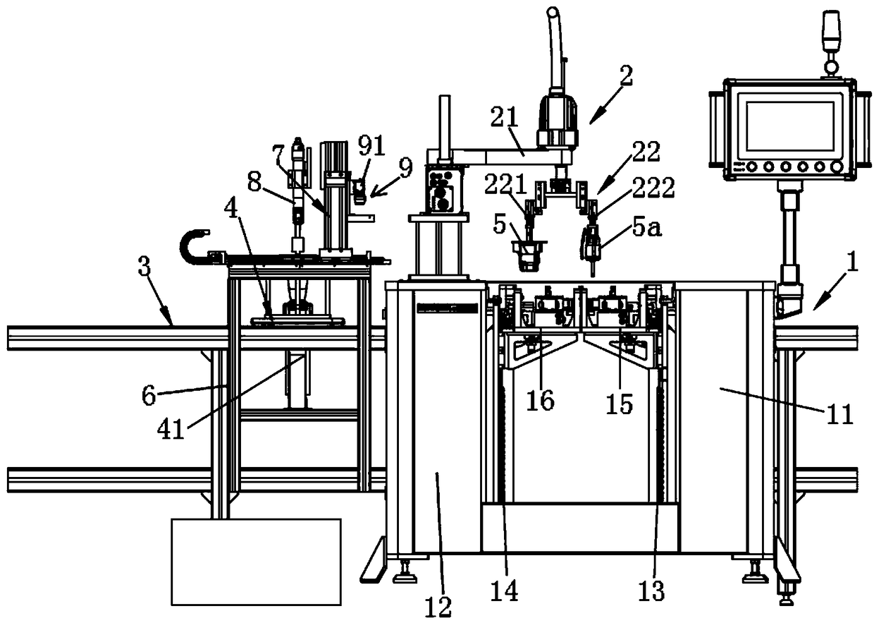
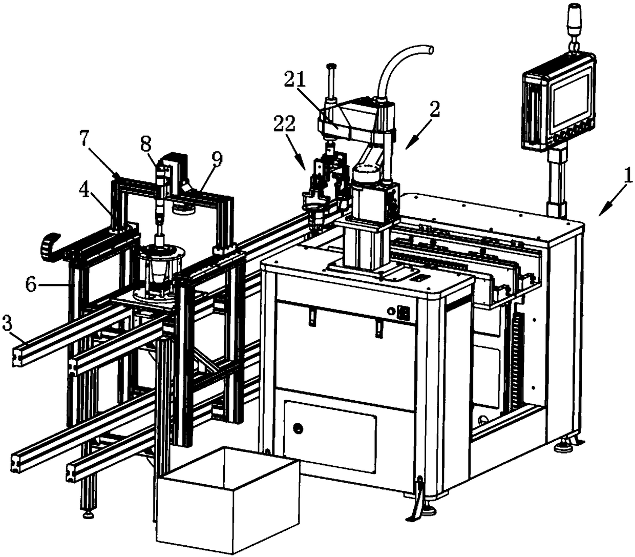
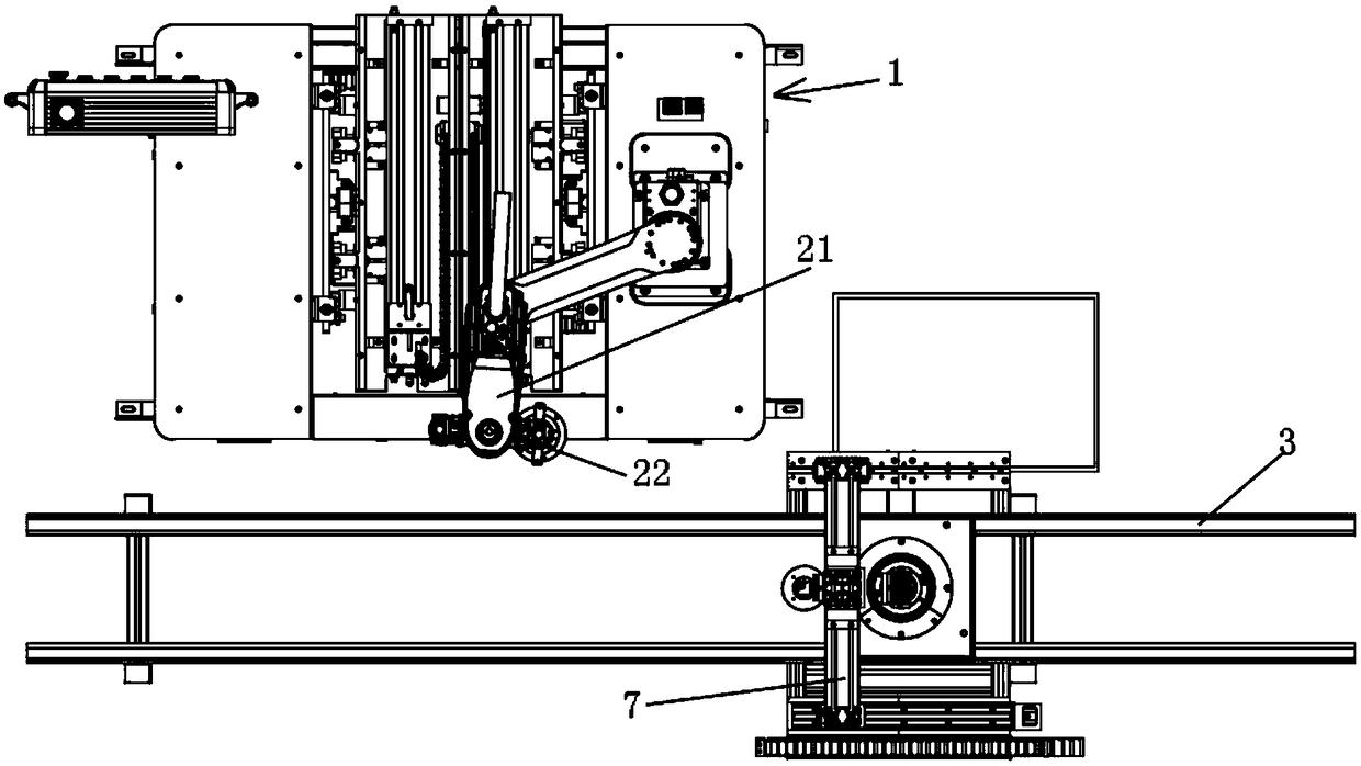
The invention relates to an automatic motor mounting device. The automatic motor mounting device comprises a feeding unit, a manipulator unit and a slide rail unit and further comprises an assembly carrier, a locating assembly, a first bracket, a second bracket and a locking mechanism, wherein the assembly carrier is movably supported on the slide rail unit; the locating assembly is detachably supported on the assembly carrier; the first bracket is located on two sides of the slide rail unit; the second bracket is movably supported on the first bracket; and the locking mechanism is supported on the second bracket. When the automatic motor mounting device provided by the invention is adopted to mount a micro motor to a product, the work efficiency can be improved greatly, the assembly precision can be increased, and the product percent of pass can be guaranteed.

Description

technical field [0001] The invention belongs to the technical field of automatic production, and in particular relates to an automatic installation device for assembling a motor. Background technique [0002] The micro motor is mainly composed of an internal rotor, a stator, a commutator and an external housing, and the commutator is connected to lead wires through terminal blocks. The application of micro motors is very extensive, involving all aspects of the national economy, national defense equipment, and human life. Micro motors can be seen in any place that requires electric drive. [0003] When assembling micro motors to products, most of the existing technologies use manual installation, which takes a lot of time and results in extremely low work efficiency. In addition, there are situations such as deviation of the installation position in manual operation, the installation accuracy is low, and the probability of defective products is high. Contents of the invent...

Claims


Application Information

Patent Timeline
IPC IPC(8): B23P19/00
CPCB23P19/00B23P19/001
Inventor 水仕淼陈腾
Owner NINGBO SUNNY INTELLIGENT TECH CO LTD
Learn More