Insert fixation device at core-pulling forming position of injection mold

A technology for injection molds and fixtures, applied in the direction of coating, etc., can solve problems such as complex structures, achieve the effects of simplifying the production process, overcoming the complexity of the reset action mechanism, and improving the appearance quality

Pending Publication Date: 2018-10-12
JIANGSU ZHONGTIAN TECH CO LTD
View PDF0 Cites 3 Cited by
  • Summary
  • Abstract
  • Description
  • Claims
  • Application Information

AI Technical Summary

Problems solved by technology

[0003] In order to solve the technical problem in the existing technology that the structure is complex, iron inserts need to be embedded in the core-pulling molding, and the A and B plates have no effective support or clamping, only the plastic parts can be injected first and then the inserts are melted. The invention provides an insert fixing device at the

Method used


Image

  • Insert fixation device at core-pulling forming position of injection mold
  • Insert fixation device at core-pulling forming position of injection mold

Examples


Embodiment Construction

[0019] In order to deepen the understanding of the present invention, the present invention will be further described below in conjunction with the embodiments and accompanying drawings. The embodiments are only used to explain the present invention and do not constitute a limitation to the protection scope of the present invention.

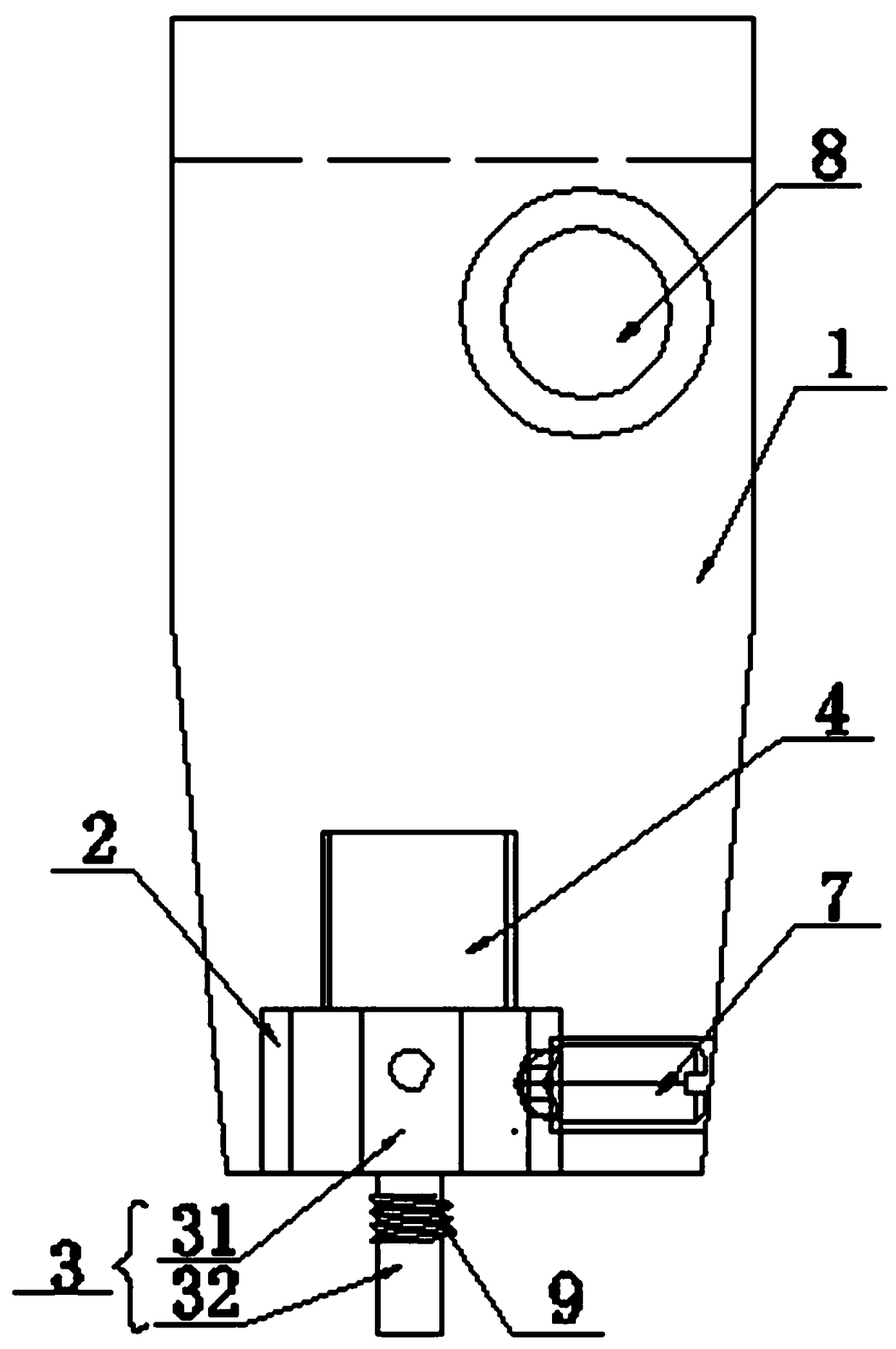
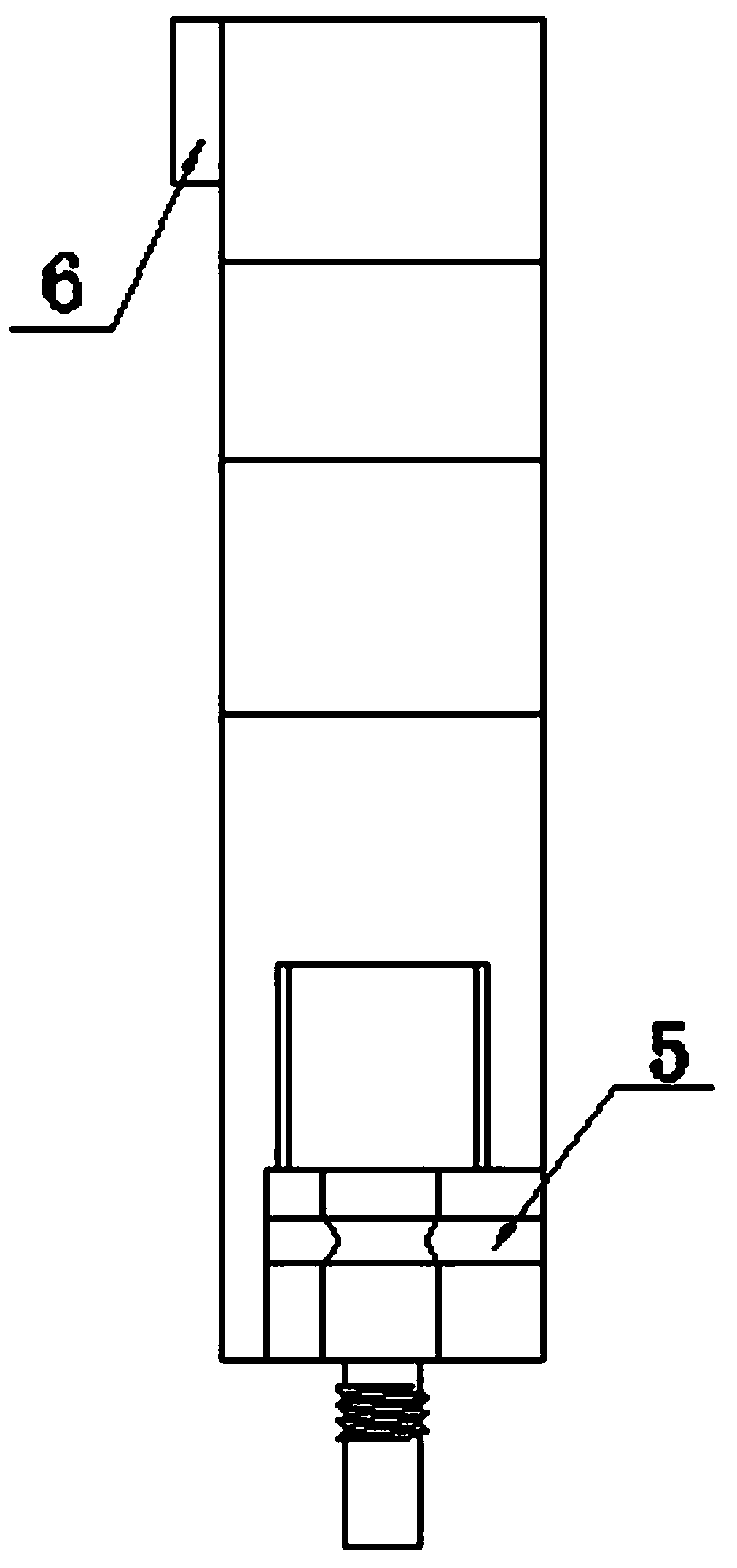
[0020] Such as figure 1 with figure 2 As shown, an insert fixing device at the core-pulling forming part of an injection mold includes a slider insert 1, an insert 2 and a magnet 4 are arranged inside the slider insert 1, and the insert 2 is located at the front end of the slider insert 1. The insert 2 is in the shape of a cuboid, and the two adjacent surfaces of the rectangular parallelepiped insert 2 are respectively located in the same plane as the two adjacent surfaces of the slider insert 1, and the insert 2 is fixed on the slider insert by the wedge block 7. In the block 1, one end of the wedge block 7 is fixed with the inner wall of the ...


PUM


Abstract

The invention discloses an insert fixation device at a core-pulling forming position of an injection mold. The insert fixation device at the core-pulling forming position of the injection mold comprises a slider insert block which is internally provided with an insert pin and a magnet; an insert block is further arranged in the slider insert block; the magnet is embedded in the slider insert block; and one end of the magnet is connected with the insert block. The insert fixation device at the core-pulling forming position of the injection mold has the beneficial effects that an insert is fixedin the manner that the insert pin is magnetized by the magnet, the difficulty that according to an insert fixing manner in the prior art, a resetting action mechanism is complex, operating and running are not reliable, and consequently the insert cannot be installed at the core-pulling forming position is overcome, and the purposes of simplifying the existing production procedure of an insert workpiece, making operating and running easier and more reliable, and improving the product appearance quality are achieved.

Description

technical field [0001] The invention relates to the field of injection mold auxiliary equipment, in particular to an insert fixing device at the core-pulling forming part of an injection mold. Background technique [0002] In the injection molds of the prior art, for those with complex structures, A and B boards are movable, one or more places need to be core-pulled and molded, and iron inserts need to be embedded in the molded places, usually the plastic parts are injected first, and then reused. A technical solution for the electric soldering iron to melt the insert into the plastic product. This technical solution has the following defects: the hot-melt insert will damage the surface of the plastic part and affect the appearance quality of the plastic product, which is not allowed for plastic products with appearance requirements; the accuracy of the hot-melt insert is general, generally only controlled at 10 wires In addition, it is difficult to meet the requirements fo...

Claims


Application Information

Patent Timeline
IPC IPC(8): B29C45/14B29C33/16B29K705/12
CPCB29C45/14065B29C33/16B29K2705/12
Inventor 程泽郭娟许春娇
Owner JIANGSU ZHONGTIAN TECH CO LTD
Why Eureka
Try Eureka