
Translation door

A technology for sliding doors and door panels, applied in the field of sliding doors, can solve the problems of structural damage to the sliding door, inconvenient installation process, short service life, etc., to avoid shaking, prevent mosquitoes from entering, and facilitate installation.

Pending Publication Date: 2018-10-12
安徽晶鹏智能装备科技有限公司
View PDF0 Cites 4 Cited by
  • Summary
  • Abstract
  • Description
  • Claims
  • Application Information

AI Technical Summary

Problems solved by technology

[0004] 1. Due to the large number of people entering and leaving the community every day, the sliding door needs to be opened repeatedly in a day, resulting in a short service life and requiring specialized personnel to perform regular maintenance, resulting in increased maintenance costs in the later period;
[0005] 2. The beam of the existing sliding door is usually made of metal, which is of high quality and extremely inconvenient during installation;
[0006] 3. When the sliding door encounters people who urgently need to enter the community during the closing process, its automatic sensing range is small, and it is easy for the sliding door to pinch residents and cause damage to the structure of the sliding door;
[0007] 4. The structure of the sliding door in the prior art is relatively single, and advertisements cannot be flexibly placed on the door body, and its aesthetics and practicability are not strong

Method used


Image

  • Translation door
  • Translation door
  • Translation door

Examples


Embodiment Construction

[0040] The following will clearly and completely describe the technical solutions in the embodiments of the present invention with reference to the accompanying drawings in the embodiments of the present invention. Obviously, the described embodiments are only some, not all, embodiments of the present invention. Based on the embodiments of the present invention, all other embodiments obtained by persons of ordinary skill in the art without making creative efforts belong to the protection scope of the present invention.

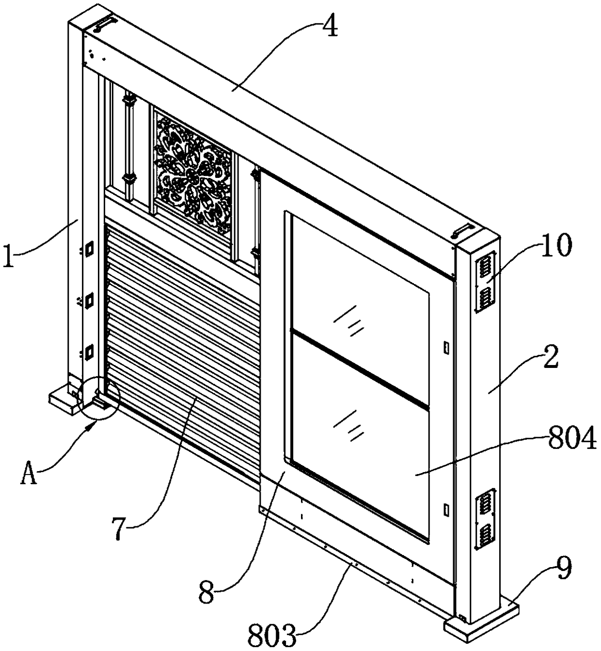
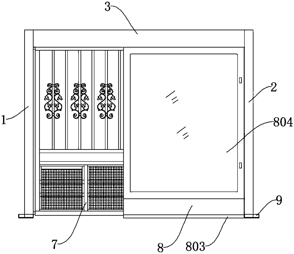
[0041] see Figure 1-10 , the present invention provides a technical solution: a translational door, including a main column 1 and an auxiliary column 2, a beam 3 is fixed between the main column 1 and the auxiliary column 2, and the lower end of the beam 3 is fixed on the side close to the auxiliary column 2. There is a light box 8, and the other side of the beam 3 is fixed with a motor integration seat 5, and a gear 6 is movable on the motor integration seat...


PUM

PropertyMeasurementUnit
Thicknessaaaaaaaaaa
Diameteraaaaaaaaaa
Thicknessaaaaaaaaaa

Abstract

The invention discloses a translation door which comprises a main stand column and an assistant stand column; a beam is arranged between the main stand column and the assistant stand column; a light box is arranged on the side, close to the assistant stand column, of the lower end of the beam; a motor integration seat is fixedly arranged on the other side of the beam; the motor integration seat ismovably provided with a gear; the gear is driven by a servo motor; the gear meshes with a rack plate; the rack plate is fixedly mounted on the inner side of the upper end of a movable door body; andone side of the movable door body movably positioned in the light box in a penetrating mode. Hook bolts are fixedly arranged on the inner lateral sides of the upper ends of the main stand column and the assistant stand column; and the hook bolts are movably clamped into bolt grooves on the two lateral end faces of the beam. Due to the heavy weight of the beam, in the prior art, the beam needs to be lifted by two persons when mounted and then screws are mounted, and time and labor are wasted; according to the translation door, the hook type beam is adopted, specifically, the beam can be hung onthe hook bolts on the inner sides of the main stand column and the assistant stand column in an inclined mode and then the person leaves the beam and fixes the screws, so that installation is convenient.

Description

technical field [0001] The invention relates to the technical field of translation doors, in particular to a translation door. Background technique [0002] Most of the sliding doors are electric sliding doors, which have the characteristics of multi-function. The door body has strict requirements on wind load resistance, and is suitable for installation on various factory building structures. This kind of door leaf can be switched manually or electrically. The number of controllable door leaves is not too much, generally single track. It is divided into two types: lower load-bearing and upper load-bearing. [0003] At present, the sliding doors are mostly used in the entrance and exit doors of the community. They are usually card-swiping sliding doors with a high degree of automation. Open it to allow residents to enter. At present, this technology is relatively mature in this field, but in use, we can find that the translation door in the prior art has the following pro...

Claims


Application Information

Patent Timeline
IPC IPC(8): E06B11/02E06B7/28E05D13/00E05F5/06G09F23/00G09F13/04
CPCG09F13/0413G09F23/00E05D13/00E05F5/06E06B7/28E06B11/02E06B11/021E06B11/026G09F13/0468
Inventor 胡四九
Owner 安徽晶鹏智能装备科技有限公司
Learn More