Modeling structure of non-axisymmetric end wall of local ball impression on lower end wall of front edge of movable blade of gas turbine

An end wall shape, non-axisymmetric technology, applied in the direction of blade support components, engine components, machines/engines, etc., can solve the problem of increasing the circumferential pressure fluctuation of the mainstream, increasing the gas intrusion into the disk cavity, and increasing the total pressure loss of the moving blade and other problems to achieve the effects of reducing pressure fluctuations, improving heat transfer stability, and improving sealing performance

Active Publication Date: 2018-10-12
XI AN JIAOTONG UNIV
View PDF3 Cites 3 Cited by
  • Summary
  • Abstract
  • Description
  • Claims
  • Application Information

AI Technical Summary

Problems solved by technology

The end wall shape of the concave wall surface will lead to a decrease in the local pressure at the leading edge of the rotor blade, reduce the main flow circumferential pressure fluctuation, and reduce the gas intrusion into the disk cavity; the end wall shape of the convex wall surface will cause the stagnation area of ​​the rotor blade leading edge to move forward, increasing the local pressure , increase the main flow circumferential pressure fluctuation, and increase the gas intrusion into the disk cavity
At the same time, the end wall shape of the leading edge of the rotor bla

Method used


Image

  • Modeling structure of non-axisymmetric end wall of local ball impression on lower end wall of front edge of movable blade of gas turbine
  • Modeling structure of non-axisymmetric end wall of local ball impression on lower end wall of front edge of movable blade of gas turbine
  • Modeling structure of non-axisymmetric end wall of local ball impression on lower end wall of front edge of movable blade of gas turbine

Examples


Embodiment Construction

[0035] The present invention will be further described in detail below in conjunction with the accompanying drawings and technical principles.

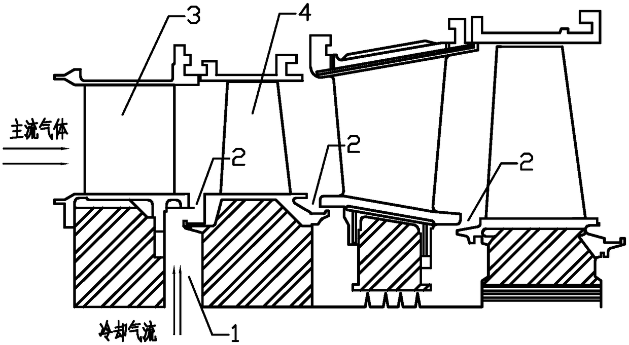
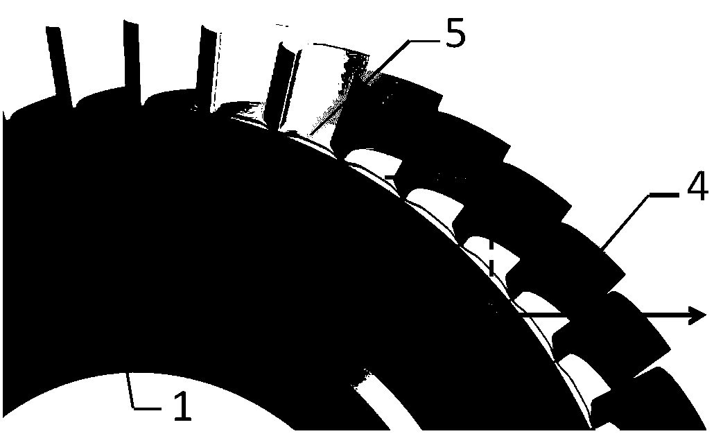
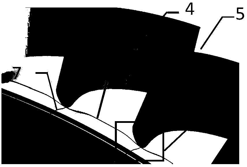
[0036] see Figure 1 to Figure 7 , the local spherical concave non-axisymmetric end wall modeling structure of the lower end wall of the leading edge of the gas turbine moving blade provided by the present invention, the local spherical concave non-axisymmetric end wall modeling structure 6 is arranged in the gas turbine rotary-stationary disk cavity 1 and There are 5 places on the lower end wall of the leading edge of the high-pressure stage of the gas turbine with radial rim seal structure 2; the lower end wall 5 of the leading edge of the moving blade is non-axisymmetrically shaped, so that the lower end wall 5 of the leading edge of the moving blade is partially recessed, The largest depression 9 of the end wall is located at the leading edge 10 of the moving blade.

[0037] Specifically, see Figure 2 to Figure 4 , different fr...


PUM


Abstract

The invention discloses a modeling structure of a non-axisymmetric end wall of a local ball impression on the lower end wall of the front edge of a movable blade of a gas turbine. The modeling structure of the non-axisymmetric end wall of the local ball impression is arranged on the lower end wall of the front edge where a rotary-static disc cavity of the gas turbine is in contact with a high pressure stage movable blade of the gas turbine of a radial rim sealing structure. Non-axisymmetric end wall modeling is carried out on the lower end wall of the front edge of the movable blade by means of an end wall modeling axial control line and an end wall modeling circumferential control line. Main flow gas forms a near wall vortex in the upstream of the front edge of the movable blade by meansof the local ball impression end wall formed by the modeling structure of the non-axisymmetric end wall of the local ball impression, so that the pressure flotation in the circumferential direction ofa main flow near a sealing outlet of a rim is reduced effectively, and therefore, the invasion degree of gas is reduced, the temperature of a turbine disc is reduced, and the heat transfer stabilityof the turbine disc is improved. Meanwhile, the efficiency loss increased by end wall modeling is controlled to a very small degree by means of a relatively small sunken degree, and the influence on integral operation of the turbine is very small.

Description

technical field [0001] The invention relates to a non-axisymmetric end wall molding structure, in particular to a gas turbine with the function of reducing the intrusion of gas in the disk cavity used in the gas turbine with the rotary-static disk cavity structure and the high-pressure stage of the high-temperature steam turbine. The local spherical concave non-axisymmetric end wall shape structure of the lower end wall of the leading edge of the translation blade. Background technique [0002] In axial-flow turbomachinery such as aero-engines, heavy-duty gas turbines, supercritical and ultra-supercritical steam turbines, after high-temperature gas flows through the high-pressure stage vanes, due to the interaction between the vane wake and the leading edge of the rotor blades, the rotor and static parts High pressure and low pressure areas alternate in the circumferential direction and change constantly with the rotation of the rotor blades are formed near the gap. In the ...

Claims


Application Information

Patent Timeline
IPC IPC(8): F01D5/14
CPCF01D5/141F01D5/147
Inventor 李军程舒娴李志刚
Owner XI AN JIAOTONG UNIV
Why Eureka
Try Eureka