
Wafer cleaning device and wafer cleaning method

A technology for cleaning devices and wafers, which is applied in the manufacture of electrical components, circuits, semiconductors/solid-state devices, etc. It can solve problems such as wafer defects, achieve the effects of shortening the cycle, increasing the horizontal thrust, and relieving the pressure

Active Publication Date: 2021-11-05
INST OF MICROELECTRONICS CHINESE ACAD OF SCI +1
View PDF6 Cites 0 Cited by
  • Summary
  • Abstract
  • Description
  • Claims
  • Application Information

AI Technical Summary

Problems solved by technology

[0013] The main purpose of the present invention is to provide a wafer cleaning device and a wafer cleaning method to solve the problem that the deionized water nozzle in the prior art is easy to cause defects on the wafer

Method used


Image

  • Wafer cleaning device and wafer cleaning method
  • Wafer cleaning device and wafer cleaning method
  • Wafer cleaning device and wafer cleaning method

Examples


Embodiment 1

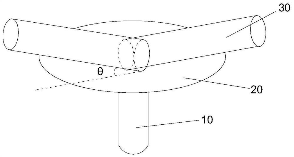
[0054] The wafer cleaning device provided in this embodiment is as Figure 5 As shown, base 10 has a first surface for carrying wafer 20, and the wafer cleaning device includes two deionized water nozzles 30, each deionized water nozzle 30 is arranged above the first surface of base 10, each deionized The angle between the spraying direction of the water nozzle 30 and the first surface is 0°<θ<90°, one deionized water nozzle 30 has a first water outlet, the other deionized water nozzle 30 has a second water outlet, and the second deionized water nozzle 30 has a second water outlet. The outer side of the first water outlet and the second water outlet are in contact with each other, the radial sections of the first water outlet and the second water outlet are rectangular with the same shape and area, and at least one of the first water outlet The side and at least one side of the second water outlet are parallel to each other.


PUM


Abstract

The invention provides a wafer cleaning device and a wafer cleaning method. The device is used to clean the wafer absorbed by the base, the base has a first surface for carrying the wafer, the wafer cleaning device includes a plurality of deionized water nozzles, and the deionized water nozzles are arranged on the first surface of the base Above, the spraying directions of the deionized water nozzles are different, and there is an angle θ between the spraying directions of the deionized water nozzles and the first surface, 0°<θ<90°. By making the injection direction of the deionized water nozzle inclined to the wafer surface, the pressure of the deionized water on the residual defects on the wafer can also be slowed down, so that the defects in the middle are not easy to form, and the horizontal thrust on the defects can be increased to reduce the defects in the middle. There are some defects, which greatly improves the process yield; on the other hand, compared with the nozzles perpendicular to the wafer in the prior art, the above-mentioned wafer cleaning device does not require a long cleaning time, thereby shortening the development process. cycle.

Description

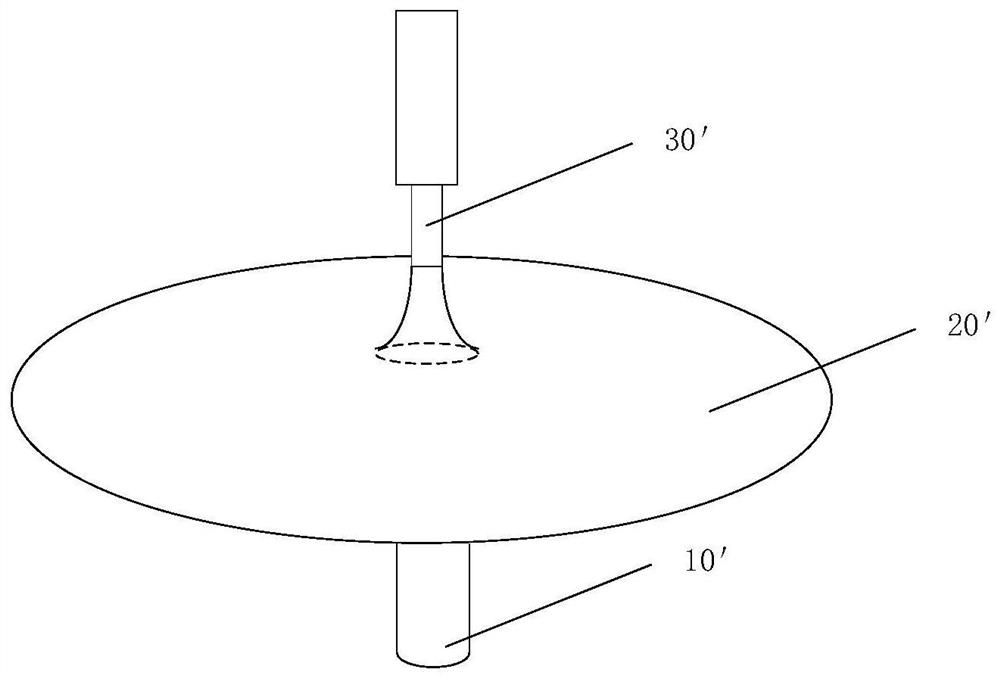
technical field [0001] The invention relates to the technical field of semiconductor technology, in particular to a wafer cleaning device and a wafer cleaning method. Background technique [0002] Traditional wafer cleaning devices such as figure 1 As shown, the base 10' adsorbs the wafer 20' on the surface, and the deionized water is vertically sprayed on the wafer surface through the deionized water nozzle 30'. When the deionized water is vertically sprayed in the middle of the wafer, the middle of the wafer is deionized The pressure F of the ionized water is easy to form defects in the middle of the wafer, and the number of defects in the middle increases with the increase of the spray speed. [0003] From the nozzle to the wafer surface, the gravitational potential energy (E p = mgh) into kinetic energy [0004] thus deduce Assume that the initial velocity of deionized water at the nozzle is v 0 , the total velocity of deionized water reaching the wafer surface...

Claims


Application Information

Patent Timeline
Patent Type & Authority Patents(China)
IPC IPC(8): H01L21/67
CPCH01L21/67051
Inventor 马玲韦亚一徐步青董立松
Owner INST OF MICROELECTRONICS CHINESE ACAD OF SCI
Learn More