
climbing machine

A rock climbing machine and drive mechanism technology, applied in the field of sports and fitness equipment, can solve problems such as limited gravity transmission structure, high assembly difficulty, sports injuries, etc., and achieve the best industrial economic benefits, improve exercise efficiency, and best transmission performance.

Inactive Publication Date: 2019-11-29
叶永松
View PDF4 Cites 0 Cited by
  • Summary
  • Abstract
  • Description
  • Claims
  • Application Information

AI Technical Summary

Problems solved by technology

[0003] At present, the common stepping machine structure on the market, the transmission mechanism between the left and right side pedals and the resistance wheel is a cable transmission type. However, this design still has the following problems in practical applications: the cable transmission The type is limited by its gravity transmission structure, so in order to achieve the expected gravity state, it must be set as a two-stage transmission type, but this will inevitably lead to high cost, high difficulty in assembly, and the belt is easy to slip, drop, run, and break. , flipping and other disadvantages and problems
However, this design is not in line with ergonomics. Just like walking, the hands must be matched with the feet to swing back and forth in order to achieve the best balance during exercise or walking.
Of course, there are also industry players who have developed swing bars. Such a structure may improve the lack of the aforementioned steppers: however, the moving track of the free end of the swing bars of general exercise equipment is an upwardly convex arc, which still does not conform to ergonomics. Movement track
[0005] In addition, existing rock climbing machines usually use strong gravity loads to focus on the training of muscle lines, so they are not suitable for young and old people at all.
What's more, some training machines are placed in the rehabilitation department of the hospital to provide the wounded with muscle strength or muscle rehabilitation. Too strong gravity load may cause sports injuries before the rehabilitation results can be seen.

Method used


Image

  • climbing machine
  • climbing machine
  • climbing machine

Examples


Embodiment Construction

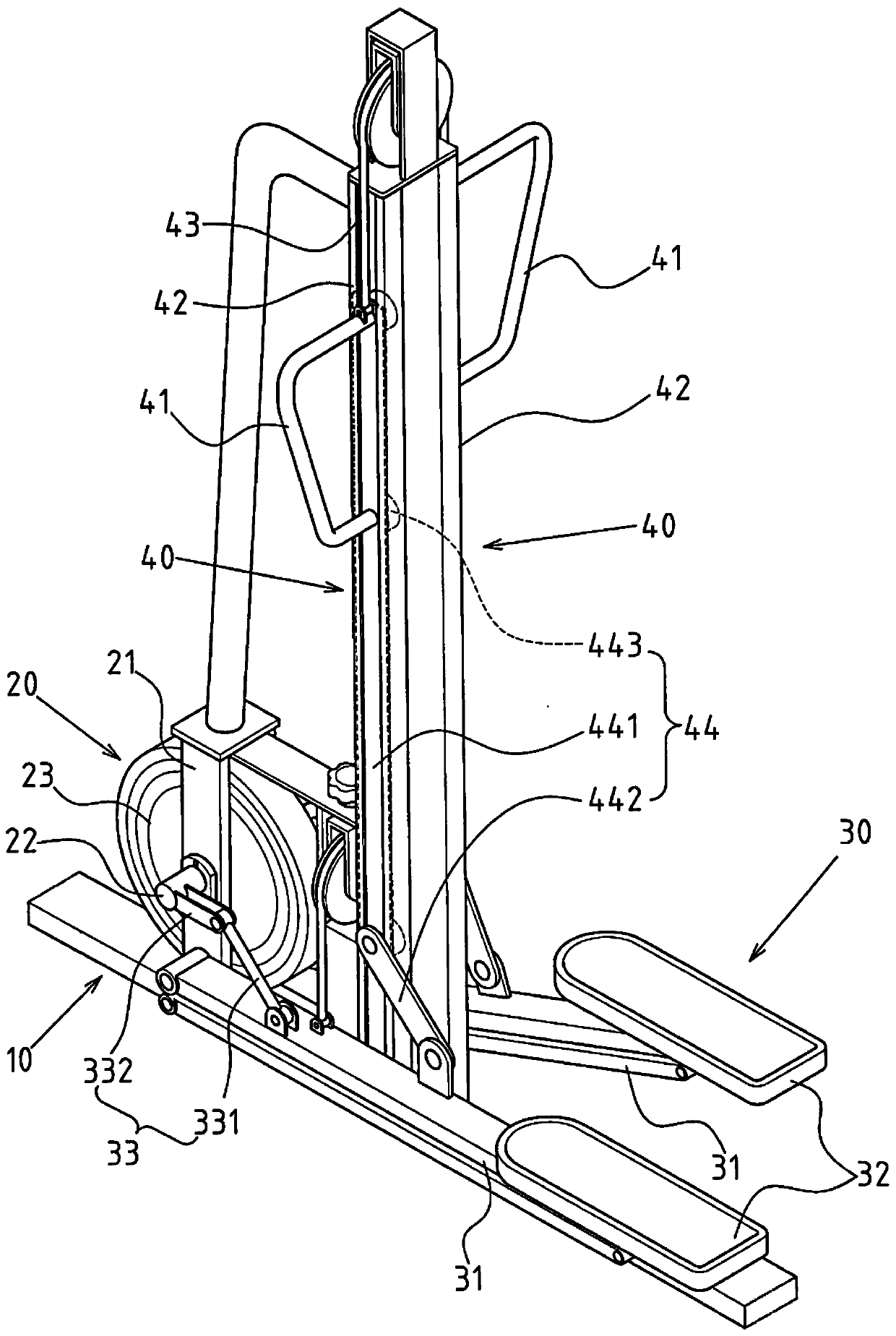
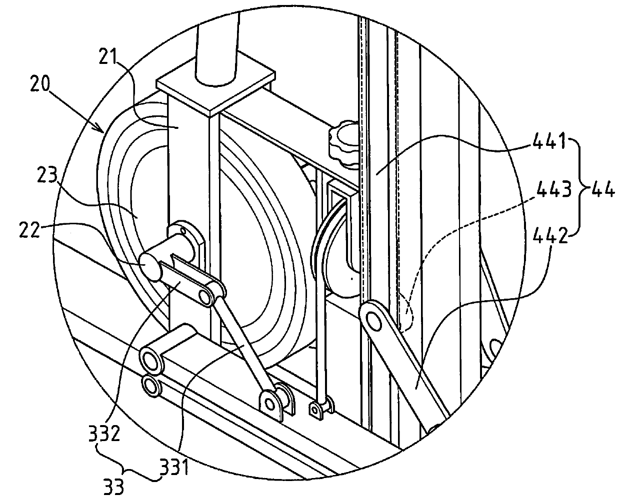
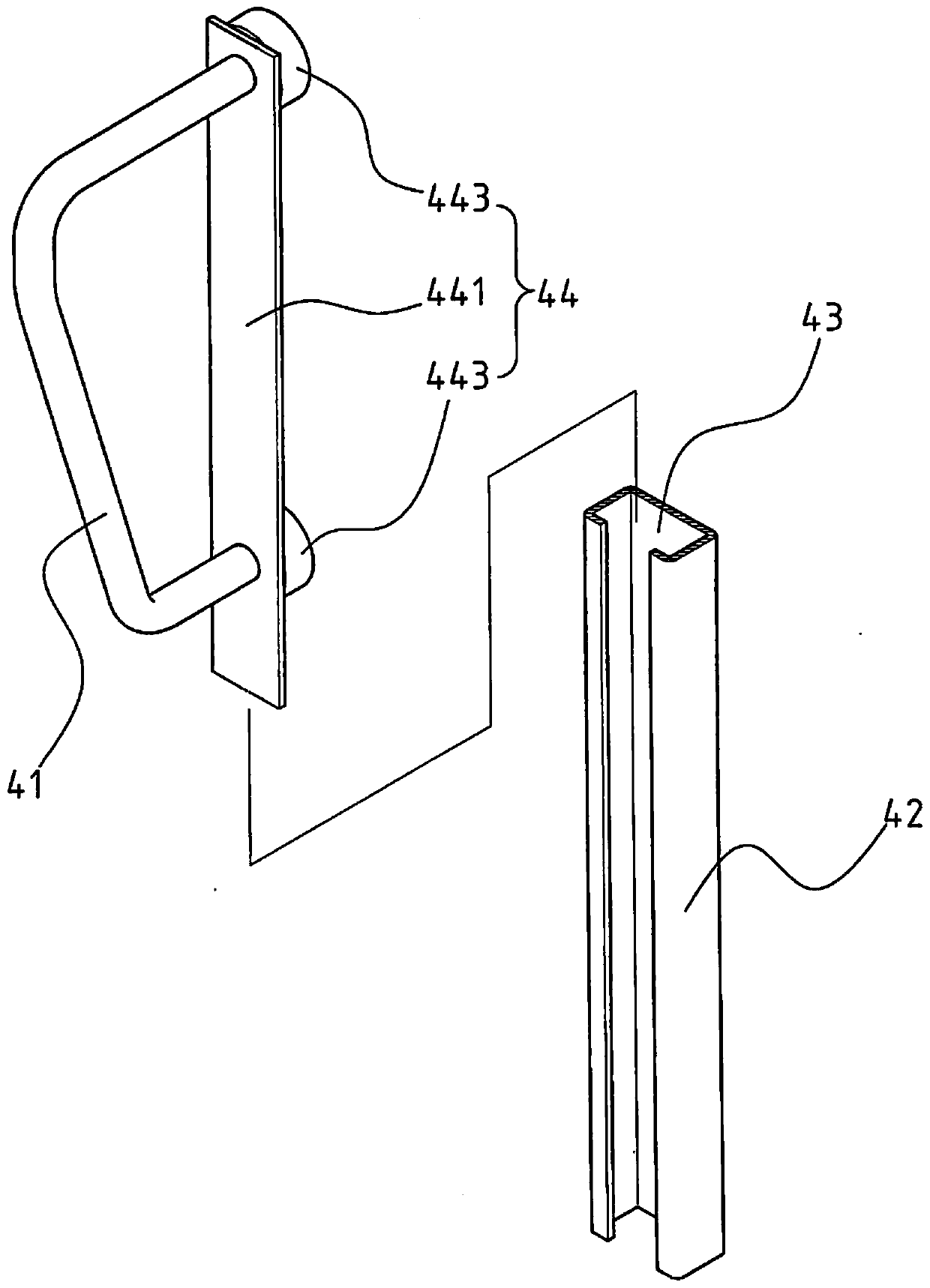
[0017] See also shown in Fig. 1, 2, 3, 4, be the preferred embodiment of rock climbing machine of the present invention, take this as an example to describe the present invention in detail, but the scope of patent protection is not limited by this structure. The rock climbing machine of this embodiment includes a base 10 placed flat on a support surface, and a damping device 20 installed on the base 10. A stepping structure 30 is respectively connected to both sides of the damping device 20, and the two sides are respectively upright and solid. The rock-climbing simulator 40 located on the base 10, the two rock-climbing simulators 40 are respectively arranged on both sides of the damping device 20, wherein the top of each rock-climbing simulator 40 is slidably provided with a holding device 41, and each The gripping devices 41 are respectively linked with the stepping structures 30 on the corresponding sides. When the two pedaling structures 30 alternately provide the pedaling...


PUM


Abstract

The invention discloses a rock climbing machine, which mainly comprises a base which is flatly placed on the supporting surface and a damping device which is arranged on the base, wherein a pedaling structure and two rock climbing simulators which are oppositely fixedly arranged on the base are each arranged at two sides of the damping device; the two rock climbing simulators are arranged at two sides of the damping device, wherein a holding device is slidingly arranged on each rock climbing simulator; and each holding device is connected to the pedaling structure at the corresponding side. The two pedaling structures, when alternately offering a pedaling function, can be linked to the corresponding holding devices so as to do reciprocating moving up and down; therefore, a function of simulating rock climbing actions is offered.

Description

technical field [0001] The invention relates to a sports fitness machine, in particular to an innovative structure combining the two sports functions of a stepper and a rock climbing machine. Background technique [0002] In the structural design of existing steppers, the left and right pedals and the resistance wheels must be connected by a transmission mechanism so that when the left and right pedals move up and down with the left and right pedals, the resistance can be transmitted. The wheel rotates and cooperates with a preset resistance device (such as a magnetic control) to achieve an appropriate resistance effect. [0003] At present, the common stepper structure on the market, the transmission mechanism between the left and right side pedals and the resistance wheel is a cable transmission type. However, this design still has the following problems in practical applications: the cable transmission The type is limited by its gravity transmission structure, so in orde...

Claims


Application Information

Patent Timeline
Patent Type & Authority Patents(China)
IPC IPC(8): A63B69/00
CPCA63B69/0048
Inventor 叶永松
Owner 叶永松
Learn More