Light matter separation device for construction waste treatment

A construction waste and separation device technology, which is applied in the direction of solid separation, separating solids from solids with air flow, chemical instruments and methods, etc., can solve the problems that the separation speed of the separation device cannot be automatically adjusted, and achieve the effect of ensuring work efficiency

Active Publication Date: 2019-12-13
池爱方
View PDF1 Cites 0 Cited by
  • Summary
  • Abstract
  • Description
  • Claims
  • Application Information

AI Technical Summary

Problems solved by technology

[0002] For example, Patent No. CN201520939342.X is a light material separation device and a light material separation device, which includes a support frame, a discharge device and a light material storage device respectively fixed on the support frame, and a light material storage device is fixed on the discharge device. Desliming vibrating screen, one side of the desliming vibrating screen is fixed with a suction pipe, one end of the suction pipe is set in a light material storage device, a storage tank is fixed in the light material storage device, and a suction fan is installed in the storage tank to store The bottom of the tank is provided with a discharge port, a light material sorter is provided directly below the discharge port, a discharge port is provided on the discharge device, and a belt conveyor is provided directly below the discharge port; the disadvantage of this utility model is that The separation speed of the separation device cannot be automatically adjusted according to the amount of material fed

Method used


Image

  • Light matter separation device for construction waste treatment
  • Light matter separation device for construction waste treatment
  • Light matter separation device for construction waste treatment

Examples


specific Embodiment approach 1

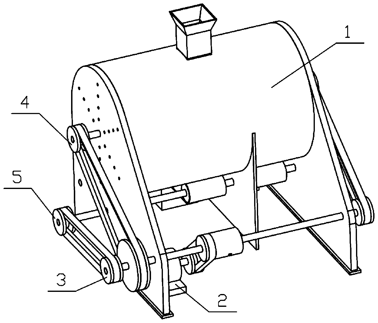
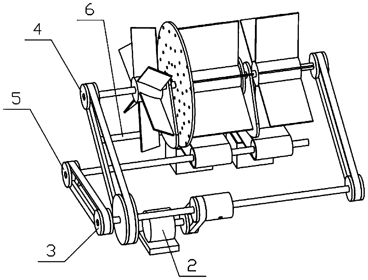
[0032] Combine below Figure 1-15Describe this embodiment, a light material separation device for construction waste treatment, including a complete machine support 1, a power mechanism 2, a differential mechanism 3, a separation mechanism 4, an active transport mechanism 5 and a passive transport mechanism 6, the power mechanism 2 A motor and a power pulley are arranged on the top, the power pulley is fixedly connected to the output shaft of the motor, the power mechanism 2 is fixedly connected to the whole machine support 1, and the differential mechanism 3 is rotatably connected to the whole machine support 1, and the differential speed Mechanism 3 and power mechanism 2 are connected by belt transmission, separation mechanism 4 is connected to the whole machine support 1 in rotation, separation mechanism 4 and differential mechanism 3 are connected by belt transmission, and active transport mechanism 5 is rotatably connected to the whole machine support 1. The transport mec...

specific Embodiment approach 2

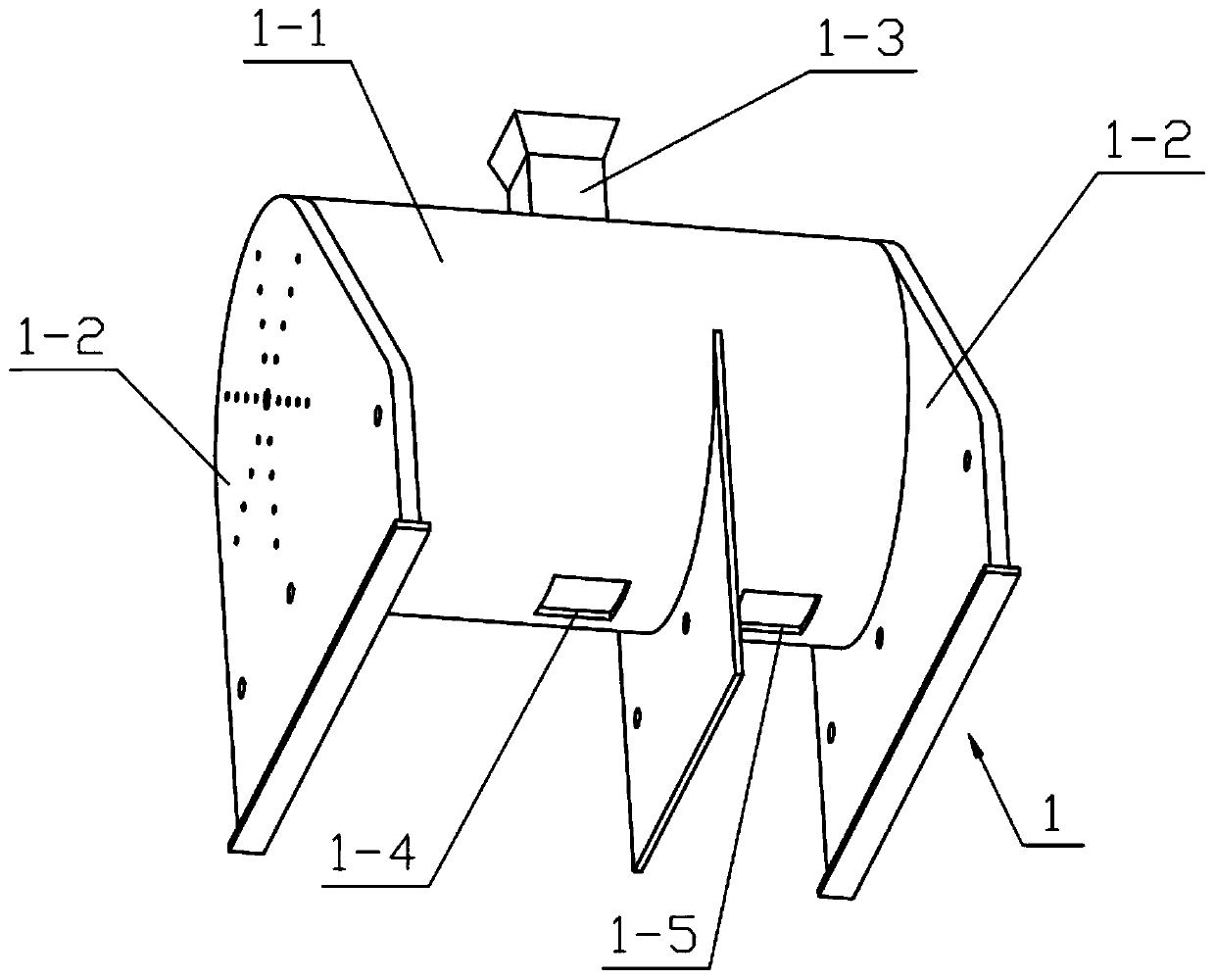
[0034] Combine below Figure 1-15 Describe this embodiment, this embodiment will further explain Embodiment 1, the whole machine support 1 includes a separation support 1-1, a side plate 1-2, a material feeding frame 1-3, a waste material outlet 1-4 and a light material outlet 1-5, two side plates 1-2 are provided, and a plurality of circular through holes I are respectively provided on the two side plates 1-2, and the two side plates 1-2 are respectively fixedly connected to the separation bracket 1- The left and right ends of 1, the feeding rack 1-3 is fixedly connected to the upper end of the separation bracket 1-1, and the waste material outlet 1-4 and the light material outlet 1-5 are respectively arranged on the left and right sides of the lower end of the separation bracket 1-1; Each side plate 1-2 is provided with a plurality of circular through holes I to ensure that the wind force generated by the fan 4-5 will not form air convection in the separation bracket 1-1 to ...

specific Embodiment approach 3

[0036] Combine below Figure 1-15 Describe this embodiment, this embodiment will further explain the second embodiment, the differential mechanism 3 includes differential shaft I3-1, differential shaft II3-2, differential pulley I3-3, differential large pulley 3-4, differential pulley II3-5, differential pulley III3-6, differential small shaft 3-7, differential bevel gear I3-8, differential bevel gear II3-9 and differential bevel gear III3- 10. The differential pulley Ⅰ 3-3 includes the differential pulley housing 3-3-1 and the differential pulley body 3-3-2, and the differential pulley body 3-3-2 is fixedly connected to the differential pulley housing The left end of 3-3-1, the differential bevel gear II 3-9 and the differential pulley III 3-6 are respectively fixedly connected to the left and right ends of the differential shaft I 3-1, the differential pulley II 3-5 and the differential bevel gear Ⅰ3-8 are respectively fixedly connected to the left and right ends of the dif...


PUM


Abstract

The invention discloses a separation device, in particular a light substance separation device for construction garbage treatment. The device comprises an overall bracket, a power mechanism, a differential mechanism, a separation mechanism, an active transportation mechanism and a passive transportation mechanism; the differential mechanism is rotationally connected to the overall bracket; the differential mechanism and the power mechanism are in transmission connection through a belt; the separation mechanism is rotationally connected to the overall bracket; the separation mechanism and the differential mechanism are in transmission connection through a belt; the active transportation mechanism is rotationally connected to the overall bracket; the active transportation mechanism and the differential mechanism are in transmission connection through a belt; the passive transportation mechanism is rotationally connected to the overall bracket; the passive transportation mechanism and theactive transportation mechanism are in transmission connection through a transportation belt; the separation speed can be automatically adjusted according to the quantity of fed construction garbage;when the construction garbage is excessive, the separation speed is slowed down to guarantee thorough removal of light substances in the construction garbage; and when the construction garbage is less, the separation speed is accelerated to guarantee the working efficiency.

Description

technical field [0001] The invention relates to a separation device, in particular to a light matter separation device for construction waste treatment. Background technique [0002] For example, Patent No. CN201520939342.X is a light material separation device and a light material separation device, which includes a support frame, a discharge device and a light material storage device respectively fixed on the support frame, and a light material storage device is fixed on the discharge device. Desliming vibrating screen, one side of the desliming vibrating screen is fixed with a suction pipe, one end of the suction pipe is set in a light material storage device, a storage tank is fixed in the light material storage device, and a suction fan is installed in the storage tank to store The bottom of the tank is provided with a discharge port, a light material sorter is provided directly below the discharge port, a discharge port is provided on the discharge device, and a belt c...

Claims


Application Information

Patent Timeline
Patent Type & Authority Patents(China)
IPC IPC(8): B07B7/01B07B11/02
CPCB07B7/01B07B11/02
Inventor 池爱方
Owner 池爱方
Why Eureka
Try Eureka