Extrusion Die Forging Process for Differential Cross Shaft Forgings

A cross shaft and differential technology, applied in forging/pressing/hammer devices, forging/pressing/hammering machinery, manufacturing tools, etc., can solve the problems of slow production tempo, scrapped forgings, heavy workload, etc., and achieve the ultimate goal The forging workload is reduced, the final forging efficiency is improved, and the effect of enhancing the strength of the journal

Active Publication Date: 2019-12-13
XUCHANG ZHONGXING FORGING +1
View PDF7 Cites 0 Cited by
  • Summary
  • Abstract
  • Description
  • Claims
  • Application Information

AI Technical Summary

Problems solved by technology

The pressing process belongs to the open billet making process, and the material distribution effect of the billet is not ideal when using the pressing process
The flash generated in the fan-shaped part between two adjacent journals is large and thick, the utilization rate of forging materials is low, and the waste is serious
[0004] 2. Due to the large burrs between the journals, a large pressure is required to make the mold close, which increases the load and energy consumption of the equipment
[0005] 3. The open die forging process has many forging processes, slow production rhythm and low production efficiency
[0006] 4. After the first crimping, the billet needs to be rotated 90 degrees before the second crimping. Due to the error in the operation of the workers, there will be deviations in the shape of the billet after crimping, which will lead to uneven distribution of the billet in the subsequent forging, resulting in forgings. It is not full of defects, so there are more waste products when using the open die forging process;
[0008] (1) Since both sides of the pre-forging body 20 are flat, when the pre-forging body 20 is placed in the lower die 22 of the final forging die, as image 3 As shown, the pre-forging cannot be positioned well, and the pre-forging body 20 is easy to move when the upper die is pressed down, which requires a high level of proficiency for the workers. The workers need to manually adjust to ensure that the pre-forging body 20 is placed in a suitable position , to ensure that the pre-forging body 20 does not move during the pressing operation, which increases the difficulty of the worker's operation, resulting in a low pass rate of final forging;
[0009] (2) Since the pre-forging body 20 is thicker and the journal 21 is shorter, the workload of final forging is relatively large, which not only shortens the life of the final forging die, but also affects the production efficiency of final forging;
[0010] 5. When finishing the final forging, since there is no positioning structure on the cross shaft of the differential, it is not easy to position and clamp on the machine tool, and it is difficult to perform finishing operations;
[0011] 6. The trimming and punching tooling has the following problems: (1) When the punch and die of the trimming die are not concentric, the four journal burrs of the differential cross shaft forging are asymmetrical, and one side The side with burrs is overcut, and the forging needs to grind 50% of the burrs. When the punch and die of the punching die are not concentric, the diameter of the inner hole does not meet the requirements of the drawing, and the forging reject rate is high; (2), Trimming and The gap between the punch and the die of the punching die is not uniform in the circumferential direction, which will lead to uneven trimming, embossing, trimming deformation and punching offset when the forging is trimmed, resulting in the scrapping of the forging; (3), When the mold is closed, the convex mold and the concave mold are prone to bumps, which will cause the mold to fall off and cause the mold to be scrapped

Method used


Image

  • Extrusion Die Forging Process for Differential Cross Shaft Forgings
  • Extrusion Die Forging Process for Differential Cross Shaft Forgings
  • Extrusion Die Forging Process for Differential Cross Shaft Forgings

Examples


Embodiment Construction

[0048] Such as Figure 4 , Figure 5 with Figure 6 As shown, the differential cross shaft forging extrusion die forging process of the present invention comprises the following steps,

[0049] (1), blanking;

[0050] (2), medium frequency induction heating;

[0051] (3), upsetting: removal of scale;

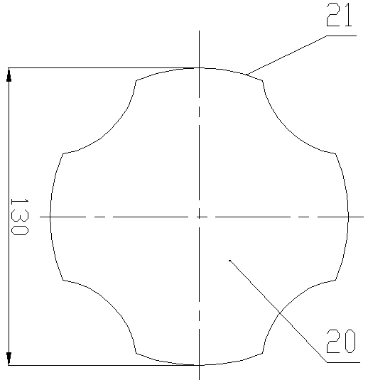
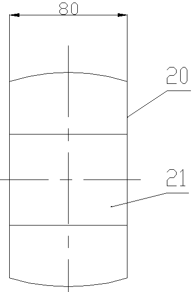
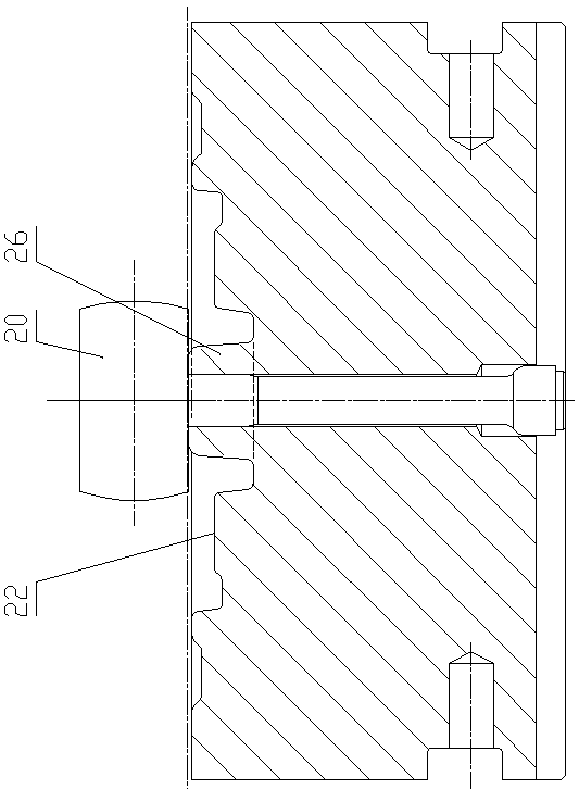
[0052] (4) Extrusion type pre-forging: Spherical protrusions are set up and down in the upper and lower mold cavities of the extrusion die, and the pier-thick billet is placed in the extrusion die, and the extruded pre-forging is extruded A cylinder 23 in the middle and four journals 21 arranged along the radial direction of the cylinder 23, the four journals 21 are arranged in a cross shape, and the bottom of the cylinder 23 protrudes downwards from where the bottoms of the four journals 21 are located. plane, the top of the cylinder 23 is on the same plane as the tops of the four journals 21, and the top of the cylinder 23 is extruded from the upper groove 24 of the top o...


PUM


Abstract

The invention discloses a differential cross shaft forging extrusion die forging process. The differential cross shaft forging extrusion die forging process comprises the steps of (1) blanking, (2) medium-frequency induction heating, (3) upsetting and scale removal, (4) extrusion pre-forging, (5) final forging, (6) edge cutting, (7) punching and (8) correction. A semi-closed radial extrusion process is adopted; through the extrusion pre-forging procedure, the blank separation effect is greatly improved, the worker operation is simple, the labor intensity is relieved, and the forging yield is increased; the extrusion separation distribution is proper, so that the life of a final forging mold is prolonged by 10-20%; flanges between two adjacent shaft necks are reduced, so that a trimming convex mold and a trimming concave mold are easily profiled, the load and the energy consumption of forging equipment are reduced, and meanwhile, the equipment failure rate is reduced; and the positionsof a punching convex mold and the trimming molds are adjusted by a movable and adjustable top plate, so that precise mold alignment is finished, and the trimming and punching precision and efficiencyare improved.

Description

technical field [0001] The invention belongs to the technical field of auto parts production, and in particular relates to an extrusion die forging process for differential cross shaft forgings. Background technique [0002] Differential cross shaft is an important part of automobile drive axle, with many specifications and varieties, and a large demand. At present, most of the domestic production adopts the open die forging process, and the process flow is: blanking - medium frequency induction heating - upsetting (removing scale) - 1 press - 2 presses - pre-forging - final forging - edge trimming - punching - correction, the following problems exist in this process: [0003] 1. The differential cross shaft forging includes a sleeve. The circumferential side of the sleeve is provided with four journals in a cross-shaped structure along the radial direction, and the forging material is a cylindrical bar. In order to ensure the four To fill the journal cavity and improve ma...

Claims


Application Information

Patent Timeline
Patent Type & Authority Patents(China)
IPC IPC(8): B21J5/00B21J5/02B21J5/08B21J5/10B21J13/02B21K1/12
CPCB21J5/002B21J5/022B21J5/027B21J5/08B21J5/10B21J13/02B21K1/12
Inventor 孟会涛郭艳珺丁圣杰高保生安伟浩陈喜乐胡卫华张恒宋航赵世启
Owner XUCHANG ZHONGXING FORGING
Why Eureka
Try Eureka