
Method for dividing working area of robot

A working area and robot technology, applied in the field of robotics, can solve the problems of robot moving speed limitation, lower robot work efficiency, complicated setting operations, etc.

Active Publication Date: 2018-10-16
TECHMAN ROBOT INC
View PDF6 Cites 5 Cited by
  • Summary
  • Abstract
  • Description
  • Claims
  • Application Information

AI Technical Summary

Problems solved by technology

Although on the robot's workbench, different colors can clearly mark the work areas with different levels of danger, but the work area of ​​the robot is a three-dimensional space, and it is impossible to use color to delineate and mark the space interface of each work area
[0005] Therefore, some existing technologies directly use the coordinate system of the robot in the working area of ​​the robot to set the coordinates to mark the separation interface, designate different operating areas of the robot, and actively limit the moving speed of the robot entering each operating area.
However, the separate interfaces marked by one-to-one coordinates are not only too complicated to set up, but also because the actual relationship between the separated interfaces marked by visual coordinates and the working areas of the physical robot is impossible, the robot is often placed in the human-machine collaboration area. , or need to work across the human-machine collaboration area, so that the moving speed of the robot is limited, and it cannot move at an optimal speed, resulting in a reduction in the working efficiency of the robot

Method used


Image

  • Method for dividing working area of robot
  • Method for dividing working area of robot
  • Method for dividing working area of robot

Examples


Embodiment Construction

[0040] In order to achieve the above-mentioned purpose, the technical means and effects thereof adopted by the present invention are now given as preferred embodiments, and are described as follows in conjunction with the accompanying drawings.

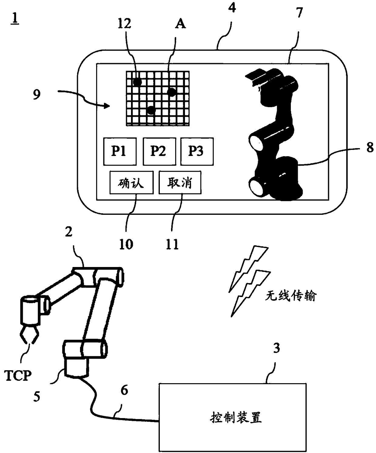
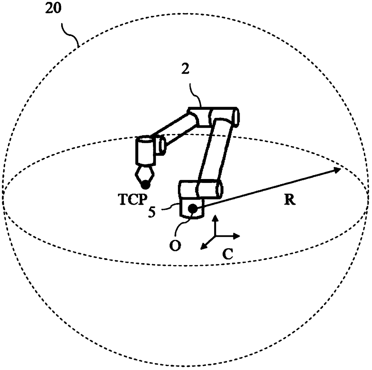
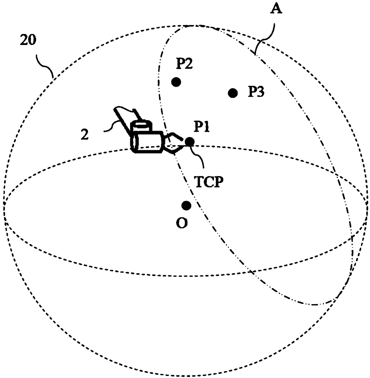
[0041] Please also refer to figure 1 , figure 2 and image 3 , figure 1 It is a schematic diagram of the robot control system of the present invention, figure 2 It is a schematic diagram of the working area of ​​the robot of the present invention, image 3 Schematic diagram of the separation interface constructed for the present invention. figure 1 Among them, the robot control system 1 of the present invention includes a robot 2, a control device 3, a man-machine interface 4, and the like. The robot 2 is a multi-axis type, the fixed end is the base 5 , and the other end is the movable Tool Center Point (TCP). The control device 3 is connected to the robot 2 via a cable 6 for controlling the robot 2 to move the tool end TCP. ...


PUM


Abstract

The invention discloses a method for dividing a working area of a robot. The method comprises the following steps that the working area of the robot is defined, a plurality of separation interfaces are built in the working area by taking non-collinear three points, when the separation interfaces are built, the separation interfaces are mutually crossed to form separation lines, the separation lines divide the separation interfaces into punctuating section surfaces and extending section surfaces, the punctuating section surfaces are connected to form a full separation interface, the full separation interface divides the working area into two operation areas, and the operation area comprising an origin coordinate of the robot is selected as a moving area so as to simplify the dividing operation.

Description

technical field [0001] The invention relates to a robot, in particular to a human-machine collaborative industrial robot, which is a method for planning areas with different moving speeds according to the degree of danger of the operator in the robot working area. Background technique [0002] The robot has the characteristics of flexible movement, precise positioning and continuous operation. Although it has become the best tool for manufacturing and assembling on the product line, there are still operations that require human-machine collaboration. In human-machine cooperation, protecting the safety of workers has become the main problem of human-machine cooperation. [0003] In order to ensure the safety of the workers in the working area of ​​the robot, existing technologies such as US20160167231 usually use optical sensors or visual devices to set safety boundaries in the working area to delineate the working area. The robot will automatically reduce its moving speed i...

Claims


Application Information

Patent Timeline
IPC IPC(8): B25J9/16
CPCB25J9/1656
Inventor 黄申栋王培睿黄识忠谢吉模蔡昀轩夏绍基
Owner TECHMAN ROBOT INC
Learn More