Cast iron swing check valve

A swing type, check valve technology, applied in valve details, control valves, valve devices, etc., can solve problems such as troublesome opening, time-consuming and laborious

Inactive Publication Date: 2018-10-16
CHIZHOU XINJIA VALVE MFG CO LTD
View PDF0 Cites 0 Cited by
  • Summary
  • Abstract
  • Description
  • Claims
  • Application Information

AI Technical Summary

Problems solved by technology

[0002] The disc of the existing swing check valve is fixed on the side of the water outlet, so the water flow direction of each check valve is fixed. When the user needs to change the direction, it needs to be disassembled and reinstalled, which is time-consuming and laborious. Some bonnets are fixed on the valve body by multiple bolts, which is very troublesome to open, so we propose a cast iron swing check valve to solve the above problems

Method used


Image

  • Cast iron swing check valve
  • Cast iron swing check valve
  • Cast iron swing check valve

Examples


Embodiment Construction

[0016] The following will clearly and completely describe the technical solutions in the embodiments of the present invention with reference to the accompanying drawings in the embodiments of the present invention. Obviously, the described embodiments are only some, not all, embodiments of the present invention. Based on the embodiments of the present invention, all other embodiments obtained by persons of ordinary skill in the art without making creative efforts belong to the protection scope of the present invention.

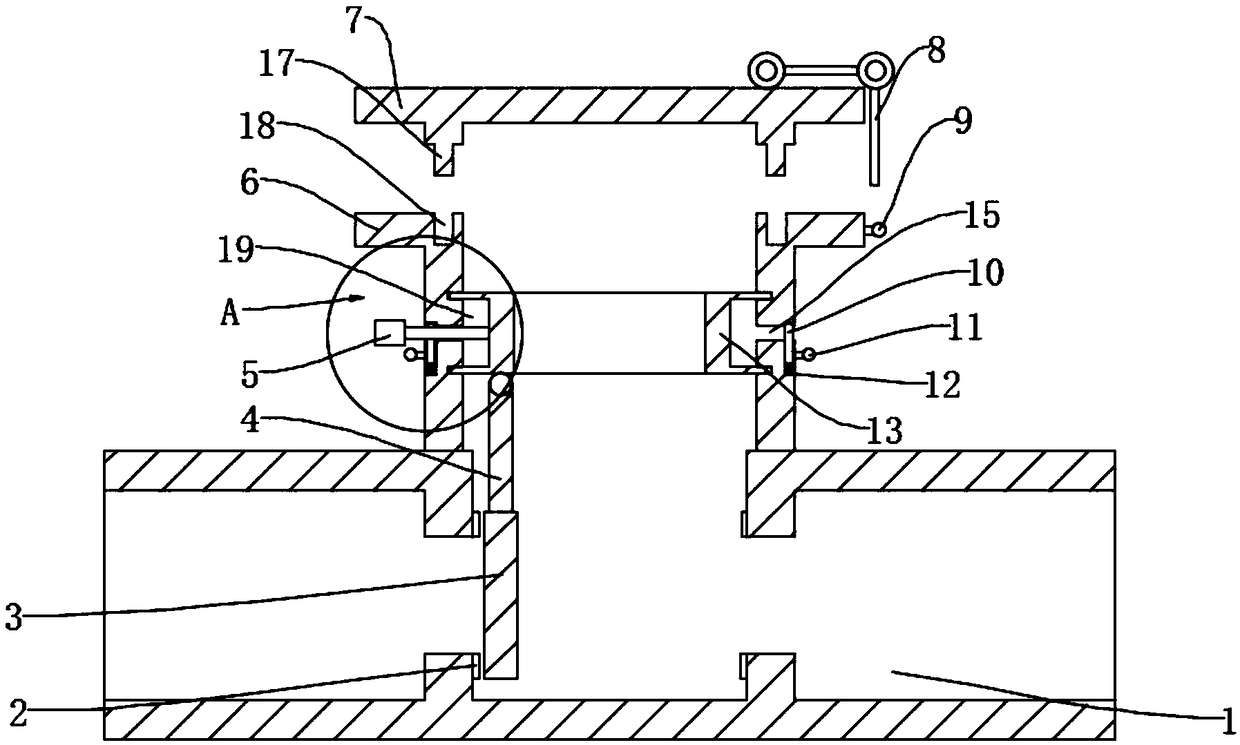
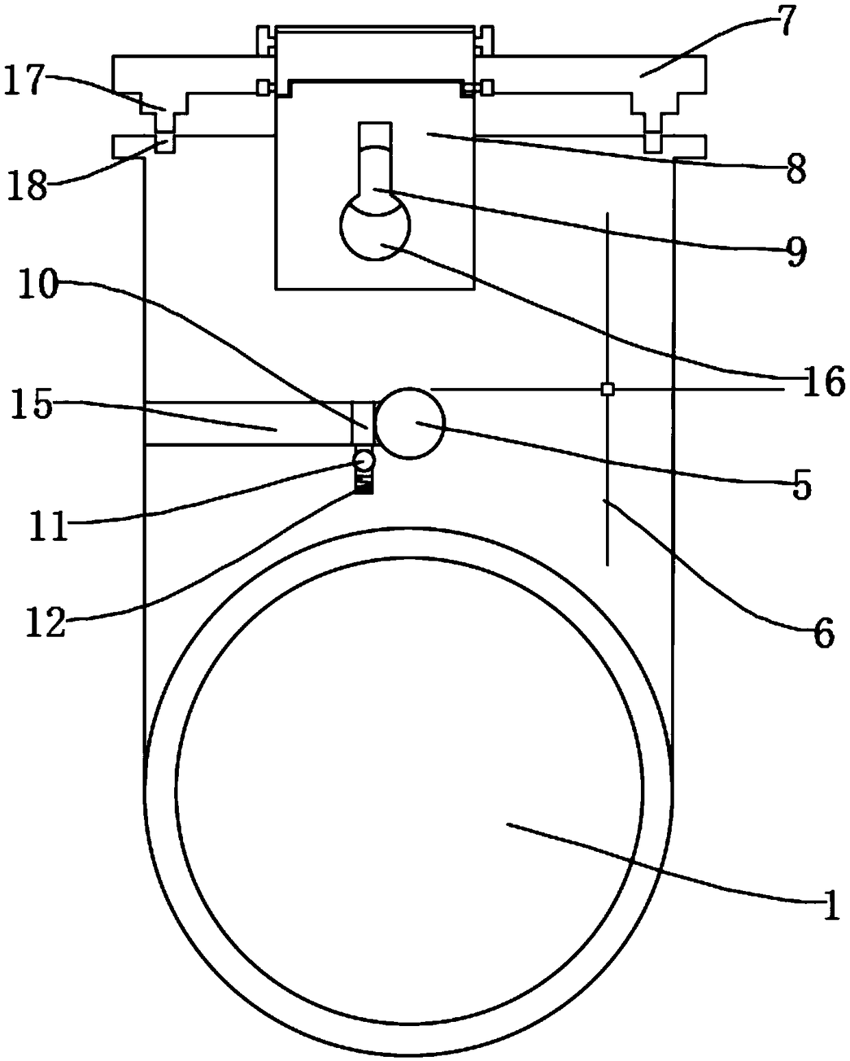
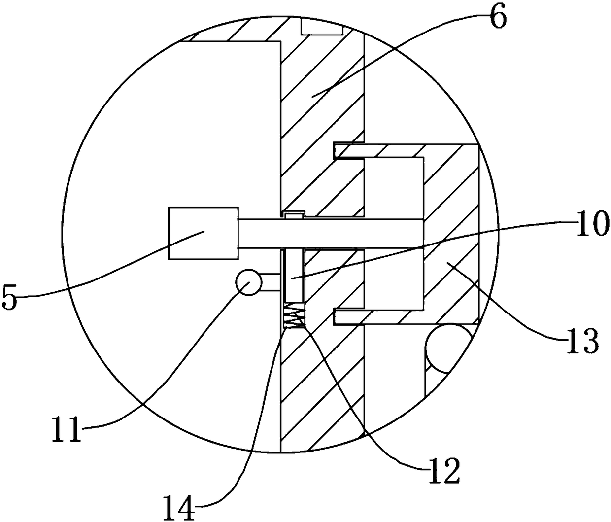
[0017] see Figure 1-3 , the present invention provides a technical solution: a cast iron swing check valve, including a water port 1, the upper end of the water port 1 is fixedly connected with a valve body 6, a sealing ring 2 is arranged inside the water port 1, and the other end of the sealing ring 2 A valve disc 3 is provided, and the valve disc 3 is a circular block structure whose diameter is larger than that of the sealing ring 2;

[0018] The upper en...


PUM


Abstract

The invention discloses a cast iron swing check valve. The cast iron swing check valve comprises a water passing opening. A valve body is fixedly connected to the upper end of the water passing opening. A seal ring is arranged inside the water passing opening. The other end of the seal ring is provided with a valve clack. A swing arm is fixedly connected to the upper end of the valve clack. An annular grooved block is hinged to the swing arm, connected to the inner wall of the valve body in a clamped manner and movably connected to the valve body. A handle is fixedly connected to the outer endof the annular grooved block. A half-ring-shaped opening is formed in the side, provided with the handle, of the valve body. The handle penetrates the valve body and is fixedly connected with the annular grooved block. A cavity is formed in the left side of the handle and internally provided with a cylinder. A hand lever is arranged at the outer end of the cylinder, penetrates the valve body andis fixedly connected with the cylinder. A spring is fixedly connected with the lower end of the cylinder. The other end of the spring is fixedly connected to the inner wall of the cavity. An annular cavity hole is formed in the upper end of the valve body. The portion, provided with the annular cavity hole, of the outer surface of the valve body is provided with buckling pillars. A valve deck is arranged at the upper end of the valve body. The inner wall of the valve deck is provided with step-shaped blocks. Hinge buckles are arranged on the upper surfaces of the step-shaped blocks.

Description

technical field [0001] The invention relates to the technical field of check valves, in particular to a cast iron swing check valve. Background technique [0002] The disc of the existing swing check valve is fixed on the side of the water outlet, so the water flow direction of each check valve is fixed. When the user needs to change the direction, it needs to be disassembled and reinstalled, which is time-consuming and laborious. Some bonnets are fixed on the valve body by multiple bolts, which is very troublesome when it needs to be opened. Therefore, we propose a cast iron swing check valve to solve the above problems. Contents of the invention [0003] The object of the present invention is to provide a cast iron swing check valve to solve the problems raised in the above-mentioned background technology. [0004] In order to achieve the above object, the present invention provides the following technical solutions: a cast iron swing check valve, including a water port...

Claims


Application Information

Patent Timeline
Patent Type & Authority Applications(China)
IPC IPC(8): F16K15/18F16K31/44
CPCF16K31/44F16K15/1821
Inventor 左红学
Owner CHIZHOU XINJIA VALVE MFG CO LTD
Why Eureka
Try Eureka