

Optical lenses and imaging equipment
An optical lens and lens technology, applied in the direction of optics, optical components, instruments, etc., can solve the problem of limited installation space, etc., and achieve the effect of reducing radial volume, large field of view, and long overall focal length
- Summary
- Abstract
- Description
- Claims
- Application Information
AI Technical Summary
Problems solved by technology
Method used
Image

Examples
no. 1 example
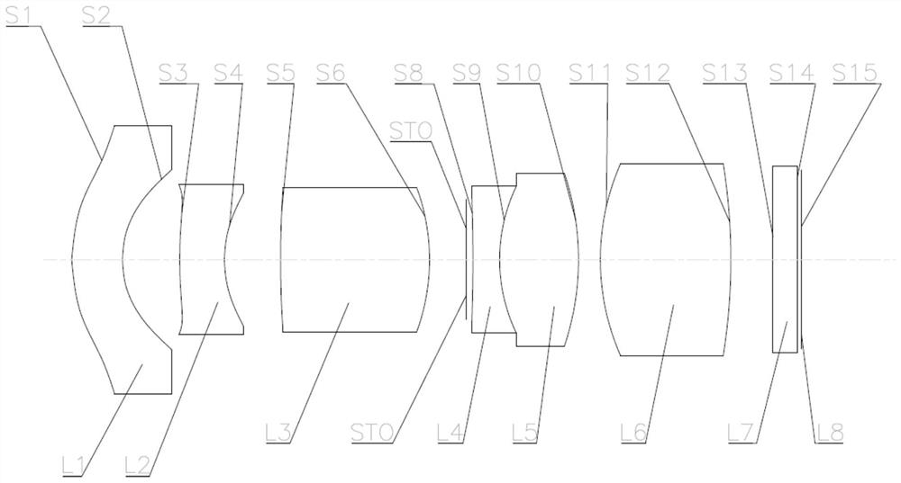
[0105] Such as figure 2 As shown, the optical lens according to the first embodiment of the present invention includes in sequence from the object side to the image side: a meniscus-shaped first lens L1 with negative refractive power, a first surface S1 convex to the object side and a concave first surface S1 The second surface S2 on the image side has a shape close to a concentric circle; the meniscus-shaped second lens L2 with negative power has a first surface S3 convex to the object side and a second surface concave to the image side S4, and the edge of its first surface S3 has an inflection point; a biconvex third lens L3 with positive refractive power has a first surface S5 convex to the object side and a second surface S6 convex to the image side; stop STO; a fourth lens L4 and a fifth lens L5 cemented to each other, wherein the fourth lens L4 is a biconcave shape with negative power, having a first surface S8 concave to the object side and a second surface S8 concave ...
no. 2 example
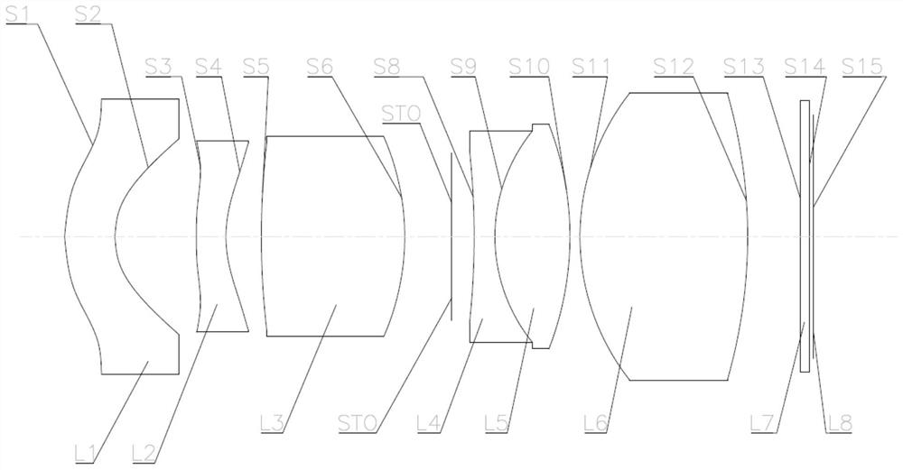
[0118] Such as image 3 As shown, the optical lens according to the second embodiment of the present invention includes in sequence from the object side to the image side: a meniscus-shaped first lens L1 with negative power, a first surface S1 convex to the object side and a concave first surface S1 The second surface S2 on the image side has a shape close to a concentric circle; the meniscus-shaped second lens L2 with negative power has a first surface S3 convex to the object side and a second surface concave to the image side S4, and the edge of its first surface S3 has an inflection point; a biconvex third lens L3 with positive refractive power has a first surface S5 convex to the object side and a second surface S6 convex to the image side; stop STO; a fourth lens L4 and a fifth lens L5 cemented to each other, wherein the fourth lens L4 is a biconcave shape with negative power, having a first surface S8 concave to the object side and a second surface S8 concave to the imag...
no. 3 example
[0132] Such as Figure 4 As shown, the optical lens according to the third embodiment of the present invention includes in sequence from the object side to the image side: a meniscus-shaped first lens L1 with negative power, a first surface S1 convex to the object side and a concave first surface S1 The second surface S2 on the image side has a shape close to a concentric circle; the meniscus-shaped second lens L2 with negative power has a first surface S3 convex to the object side and a second surface concave to the image side S4, and the edge of its first surface S3 has an inflection point; a biconvex third lens L3 with positive refractive power has a first surface S5 convex to the object side and a second surface S6 convex to the image side; stop STO; a fourth lens L4 and a fifth lens L5 cemented to each other, wherein the fourth lens L4 is a biconcave shape with negative power, having a first surface S8 concave to the object side and a second surface S8 concave to the imag...
PUM
 Abstract
Description
Claims
Application Information