
Battery cover plate assembly, battery cell, battery module, power battery pack and electric automobile

A battery cover and component technology, which is applied to battery pack components, secondary battery charging/discharging, battery cover/end cover, etc. To protect the battery and other issues

Active Publication Date: 2018-10-16
BYD CO LTD
View PDF3 Cites 2 Cited by
  • Summary
  • Abstract
  • Description
  • Claims
  • Application Information

AI Technical Summary

Problems solved by technology

[0004] 1. In the initial stage of battery overcharging, the gas generated inside the battery is less, and the breaking structure cannot be disconnected in time
[0005] 2. When the internal pressure of the battery is high, the battery has already experienced thermal runaway, even if the structure is disconnected, it will not be able to protect the battery
[0006] 3. When the battery breaking pressure is high, the starting pressure increases, and the breaking structure cannot be disconnected in time; while when the breaking pressure is small, the breaking structure may break when the battery is filled with liquid or stored at high temperature
When the internal pressure of the battery is too high, the battery is often in a state of thermal runaway. Although the circuit can be broken at this time, it cannot stop the interaction between the internal materials of the battery and still cannot protect the battery.

Method used


Image

  • Battery cover plate assembly, battery cell, battery module, power battery pack and electric automobile
  • Battery cover plate assembly, battery cell, battery module, power battery pack and electric automobile
  • Battery cover plate assembly, battery cell, battery module, power battery pack and electric automobile

Examples


Embodiment Construction

[0056] Specific embodiments of the present disclosure will be described in detail below in conjunction with the accompanying drawings. It should be understood that the specific embodiments described here are only used to illustrate and explain the present disclosure, and are not intended to limit the present disclosure.

[0057] In this disclosure, unless stated otherwise, the orientation words used such as "up, down, left, right" are usually defined based on the directions of the corresponding drawings, and "inner and outer" refer to Inside and outside of the corresponding part contour. Among them, this article involves the description of the outer end, the inner end, and the inner and outer directions, such as the inner terminal, the outer terminal, the inner end surface, and the outer end surface are relative to the inside and outside of the battery along the axial direction of the pole, and relative to the ring shape. The "inside and outside" of the part, such as the oute...


PUM


Abstract

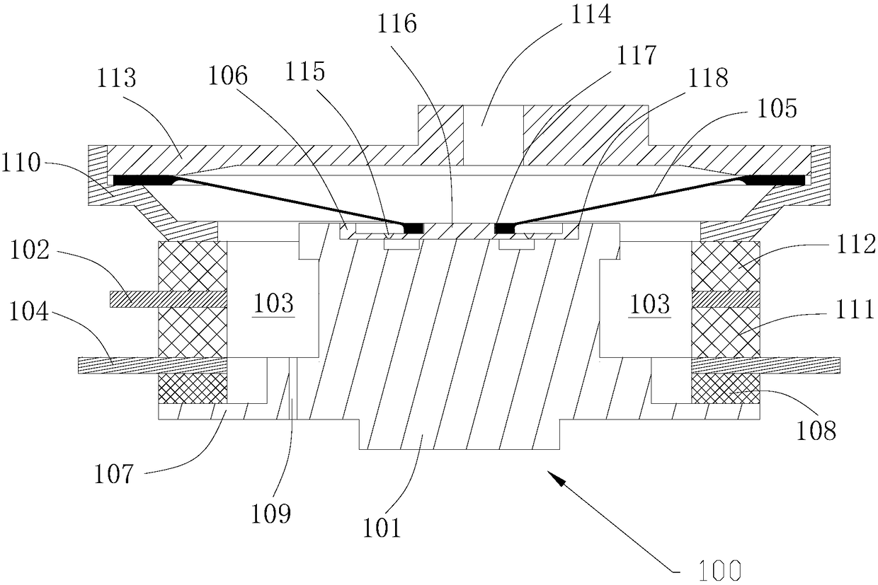
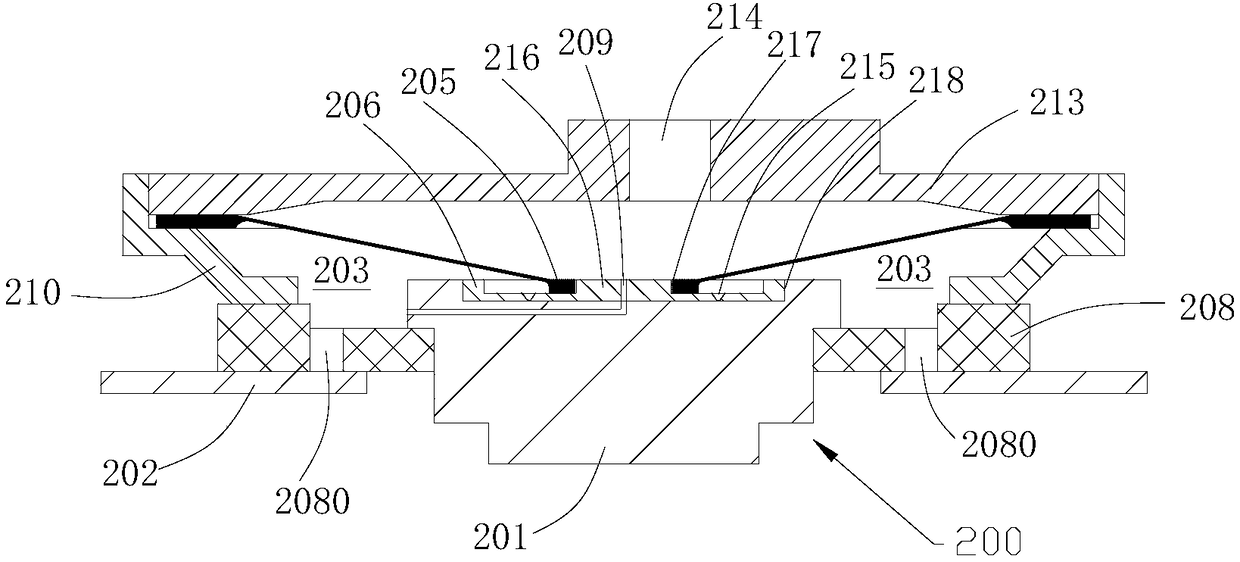
The invention relates to a battery cover plate assembly, a battery cell, a battery module, a power battery pack and an electric automobile. The battery cover plate assembly comprises a first afflux leading-out piece, a second afflux leading-out piece and a sealed package which is filled with a gas production medium and positioned on the inner side of the cover plate, wherein a first polar piece and a second polar piece which are in contact with the gas production medium respectively are arranged on the sealed package; the first polar piece is electrically connected with the first afflux leading-out piece; the second polar piece is electrically connected with the second afflux leading-out piece; and when the voltage difference between the first polar piece and the second polar piece exceedsa rated value, gas is produced by the gas production medium, the sealed package is torn under the air pressure effect of the gas, and the gas is drained from the sealed package and flows into a current interrupt structure so as to disconnect the electrical connection between an electrode inner terminal and an electrode outer terminal. The gas production of the sealing cavity inside the cover plate assembly can be independent from gas production inside the battery, so that air pressure can be established for the current interrupt structure in time, the current interrupt structure is snapped intime, and the safety of the battery is promoted.

Description

technical field [0001] The present disclosure relates to the field of batteries, in particular, to a battery cover assembly, a single battery using the battery cover assembly, a battery module including the battery, a power battery pack including the battery module, and a power battery pack including the battery Electric vehicles with power battery packs. Background technique [0002] The existing CID (Current Interrupt Device, current interruption device) technical solution is usually equipped with a pull-off structure that senses the air pressure in the battery. In extreme cases such as thermal runaway of the battery, the reaction between the internal electrolyte and the electrode material will make the A large amount of gas is generated inside the battery. When the gas inside the battery increases, the internal pressure increases, and the increased pressure makes the flipping piece in the breaking structure turn outward, thereby breaking the broken piece with local thinni...

Claims


Application Information

Patent Timeline
IPC IPC(8): H01M2/34H01M2/04H01M50/147H01M50/574H01M50/578
CPCH01M2200/20H01M50/147H01M50/578H01M50/574H01M10/44Y02E60/10
Inventor 郑卫鑫潘仪和林林朱燕
Owner BYD CO LTD
Learn More