Orthogonally polarized planar array antenna designed by adopting cross polarization inhibition method

A planar array antenna and orthogonal polarization technology, applied in the field of planar array antennas, can solve the problems of reducing the cross-polarization of the array structure, reducing the cross-polarization, and the difficulty of array design, so as to improve the cross-polarization tolerance and reduce the effect of complexity

Active Publication Date: 2018-10-16
ZHEJIANG UNIV
View PDF8 Cites 10 Cited by
  • Summary
  • Abstract
  • Description
  • Claims
  • Application Information

AI Technical Summary

Problems solved by technology

[0003] At present, papers have proposed a variety of methods for suppressing cross-polarization of multi-polarized antennas. One method is to reduce the cross-polarization of array elements by adjusting and changing the structure of the radiating element, and then reduce the cross-polarization of the array structure. The cross-mode coupler can effectively reduce the cross-polarization; another method is to make the adjacent elements in the antenna array mirror symmetrical and apply the corresponding feed phase. The cross-polarization components generated by the ports of adjacent units suppress or cancel each other, although the cross-polarization performance will be greatly improved, but when designing a large array, since each array element is symmetrical to the adjacent unit, each symmetrical feed Both may require phase inversion, so the design of the feed network is more complicated than the proposed method
For example, the reverse phase of the microstrip line feed means that the electrical length of the microstrip line increases, resulting in a longer space for the microstrip line or even a broken line, because factors such as limited space may make array design more difficult

Method used


Image

  • Orthogonally polarized planar array antenna designed by adopting cross polarization inhibition method
  • Orthogonally polarized planar array antenna designed by adopting cross polarization inhibition method
  • Orthogonally polarized planar array antenna designed by adopting cross polarization inhibition method

Examples


Embodiment 1

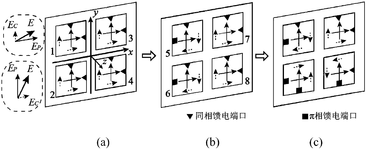
[0056] In this example, if Figure 4 As shown, the radiating unit is composed of a group of orthogonal dipole antennas, wherein one dipole antenna 10 simulates horizontal polarization, and the other dipole antenna 9 simulates vertical polarization, forming an orthogonal dipole antenna radiating unit, Such as Figure 4 (a).

[0057] Assuming vertical polarization produces a cross-polarized field in the horizontal direction than the horizontally polarized main polarization field is only 3dB lower, in which case the calculated XPD 1 、XPD 2 and XPD 3 . It can be seen from the formula that in the ideal case of the second antenna, when θ=0°, the cross-polarization fields of the second and third antennas will cancel each other.

[0058] The second antenna obtained through the mirror image symmetry in the first step, The cross-polarization isolation of horizontal polarization will be greatly improved. The third antenna obtained through the mirror image symmetry in the seco...

Embodiment 2

[0066] Embodiment 2 uses two groups of 8×4 and 8×8 dual-linearly polarized microstrip array antennas to demonstrate the above method. Each group of antennas is composed of a microstrip in-phase arrangement array and a microstrip π-phase arrangement array.

[0067] Figure 4 As shown, the radiation surface structure of the basic array is as follows Figure 4 (b), the radiating surface is connected by each radiating element 12 through an electrode laying arrangement, and is connected to the output feeding port 11 of the basic array. Back structure such as Figure 4 (c), the back is composed of multiple Wilkinson microstrip power splitters cascaded and connected to the radiation unit.

[0068] The radiating surface and its back are evenly distributed with feed networks, Figure 5 As shown, taking the 8×4 microstrip orthogonally polarized planar array antenna as an example, Figure 5 (a) and Figure 5 (b) are the equal-amplitude feed network 13 and the equal-amplitude anti-p...


PUM


Abstract

The invention discloses an orthogonally polarized planar array antenna designed by adopting a cross polarization inhibition method. The antenna is mainly formed by arranging and connecting basic arrays, wherein each basic array is formed by connecting radiating elements in a 4*4 array; each radiating element is provided with two orthogonal feed ports; various basic arrays are connected through a feed network and various radiating elements in the basic arrays are also connected through the feed network; and various radiating elements in each basic array and the orthogonal feed ports are arranged in a horizontal or vertical mirror symmetry manner or arranged in a horizontal or vertical simultaneous mirror symmetry manner. The adopted method is applicable to multiple centrosymmetric arrays, such as a circular array, a square array and a rectangular array working in linear and circular polarization modes and can be widely applied to the planar array antenna working in an orthogonal polarization mode, especially an electric large-aperture array.

Description

technical field [0001] The invention relates to a planar array antenna, in particular to an orthogonally polarized planar array antenna designed by adopting a cross-polarization suppression method, and simultaneously verifies the feasibility. Background technique [0002] Since orthogonally polarized planar array antennas allow different information to be transmitted within the same bandwidth, they currently play an important role in bandwidth-sensitive satellite communications. Using orthogonally polarized planar array antennas, the effective bandwidth of the antenna can be doubled. However, in this type of antenna, whether it is a circular polarization antenna or a linear polarization antenna, the requirements for cross polarization are very high. With the rapid development of mobile communication antenna technology, in order to avoid potential interference in satellite communication, it is very important to suppress cross-polarization technology. At the same time, in ord...

Claims


Application Information

Patent Timeline
Patent Type & Authority Applications(China)
IPC IPC(8): H01Q1/36H01Q1/38H01Q1/48H01Q1/50H01Q1/52H01Q15/24H01Q21/00H01Q21/06H01Q21/24
CPCH01Q1/36H01Q1/38H01Q1/48H01Q1/50H01Q1/523H01Q15/24H01Q21/0006H01Q21/065H01Q21/24
Inventor 王浩冉立新
Owner ZHEJIANG UNIV
Why Eureka
Try Eureka