Orthogonally polarized planar array antenna designed by cross-polarization suppression method
A planar array antenna and orthogonal polarization technology, which is applied to the combination of antenna elements with different polarization directions, antenna arrays powered separately, and specific array feeding systems, etc., can solve the problem of reducing cross-polarization of array structures and reducing Problems such as cross-polarization and lengthening of microstrip space traces, etc., achieve the effect of improving cross-polarization tolerance and reducing complexity
- Summary
- Abstract
- Description
- Claims
- Application Information
AI Technical Summary
Problems solved by technology
Method used
Image
Examples
Embodiment 1
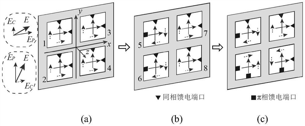
[0056] In this example, if Figure 4 As shown, the radiating unit is composed of a group of orthogonal dipole antennas, wherein one dipole antenna 10 simulates horizontal polarization, and the other dipole antenna 9 simulates vertical polarization, forming an orthogonal dipole antenna radiating unit, like Figure 4 (a).
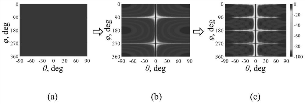
[0057] Assuming vertical polarization produces a cross-polarized field in the horizontal direction than the horizontally polarized main polarization field is only 3dB lower, in which case the calculated XPD 1 、XPD 2 and XPD 3 . It can be seen from the formula that in the ideal case of the second antenna, when θ=0°, the cross-polarization fields of the second and third antennas will cancel each other.
[0058] The second antenna obtained through the mirror image symmetry in the first step, The cross-polarization isolation of horizontal polarization will be greatly improved. The third antenna obtained through the mirror image symmetry in the second ...
Embodiment 2
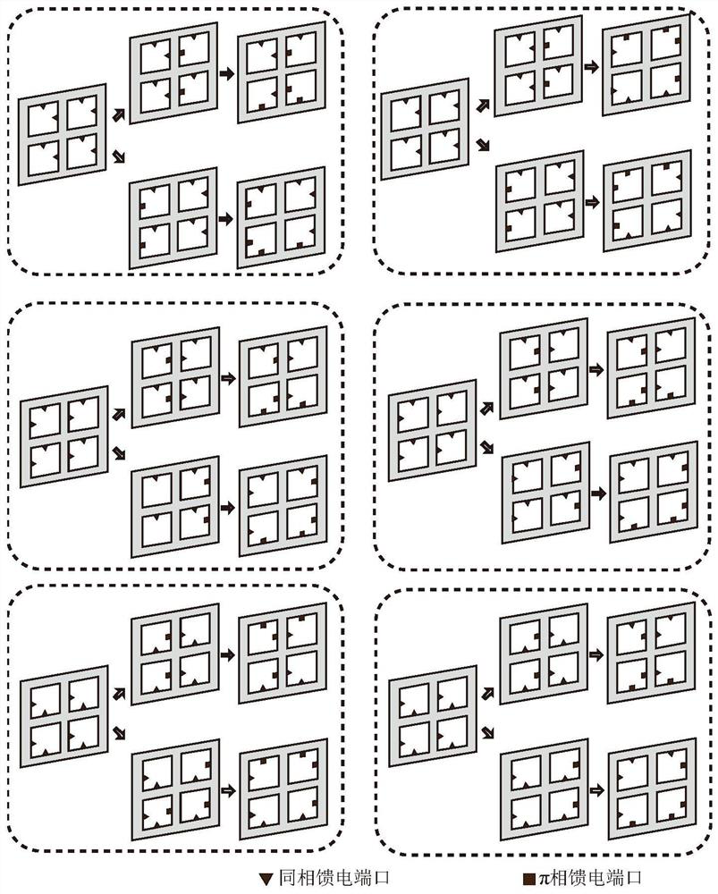
[0066] Embodiment 2 uses two groups of 8×4 and 8×8 dual-linearly polarized microstrip array antennas to demonstrate the above method. Each group of antennas is composed of a microstrip in-phase arrangement array and a microstrip π-phase arrangement array.
[0067] Figure 4 As shown, the radiation surface structure of the basic array is as follows Figure 4 (b), the radiating surface is connected by each radiating element 12 through an electrode laying arrangement, and is connected to the output feeding port 11 of the basic array. Back structure such as Figure 4 (c), the back is composed of multiple Wilkinson microstrip power splitters cascaded and connected to the radiation unit.
[0068] The radiating surface and its back are evenly distributed with feed networks, Figure 5 As shown, taking the 8×4 microstrip orthogonally polarized planar array antenna as an example, Figure 5 (a) and Figure 5 (b) are the equal-amplitude feed network 13 and the equal-amplitude anti-p...
PUM
 Abstract
Description
Claims
Application Information
 - R&D
- Intellectual Property
- Life Sciences
- Materials
- Tech Scout
- Unparalleled Data Quality
- Higher Quality Content
- 60% Fewer Hallucinations
Browse by: Latest US Patents, China's latest patents, Technical Efficacy Thesaurus, Application Domain, Technology Topic, Popular Technical Reports.
© 2025 PatSnap. All rights reserved.Legal|Privacy policy|Modern Slavery Act Transparency Statement|Sitemap|About US| Contact US: help@patsnap.com


