Novel medical equipment disinfection device

A technology of medical devices and disinfection devices, which is applied in the field of medical devices, can solve the problems of increasing the cost of use, reducing the service life of the heating net, and damage to the heating net, so as to achieve the effects of increasing the cost of use, improving product quality and reducing the service life

Inactive Publication Date: 2018-10-19
DONGGUAN SONGYAN ZHIDA IND DESIGN CO LTD
View PDF1 Cites 2 Cited by
  • Summary
  • Abstract
  • Description
  • Claims
  • Application Information

AI Technical Summary

Problems solved by technology

It can be foreseen that the development space of China's medical device industry in the future is very huge. In the existing technology, for example, the invention patent with application number 201520525977.5 includes that the disinfection outer box is provided with a disinfection inner box, and the bottom of the disinfection inner box is provided with a Frequency conversion motor, the frequency conversion motor is connected to the rotating shaft, the top of the rotating shaft is connected with an infusion pipeline, a number of nozzles are uniformly arranged on the infusion pipeline, a disc magnet is fixed in the middle of the rotating shaft, and the medical equipment is adsorbed on the periphery of the disc magnet. The lower part of the rotating shaft is fixed with a heating net, the bottom of the right side of the disinfection outer box is provided with a liquid outlet pipe, the side wall and the bottom of the disinfection inner box are provided with several liquid outlet holes, and the top of the disinfection

Method used


Image

  • Novel medical equipment disinfection device
  • Novel medical equipment disinfection device
  • Novel medical equipment disinfection device

Examples


Embodiment Construction

[0019]The following will clearly and completely describe the technical solutions in the embodiments of the present invention with reference to the accompanying drawings in the embodiments of the present invention. Obviously, the described embodiments are only some, not all, embodiments of the present invention. Based on the embodiments of the present invention, all other embodiments obtained by persons of ordinary skill in the art without making creative efforts belong to the protection scope of the present invention.

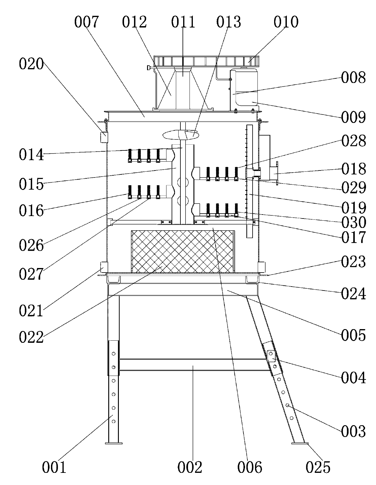
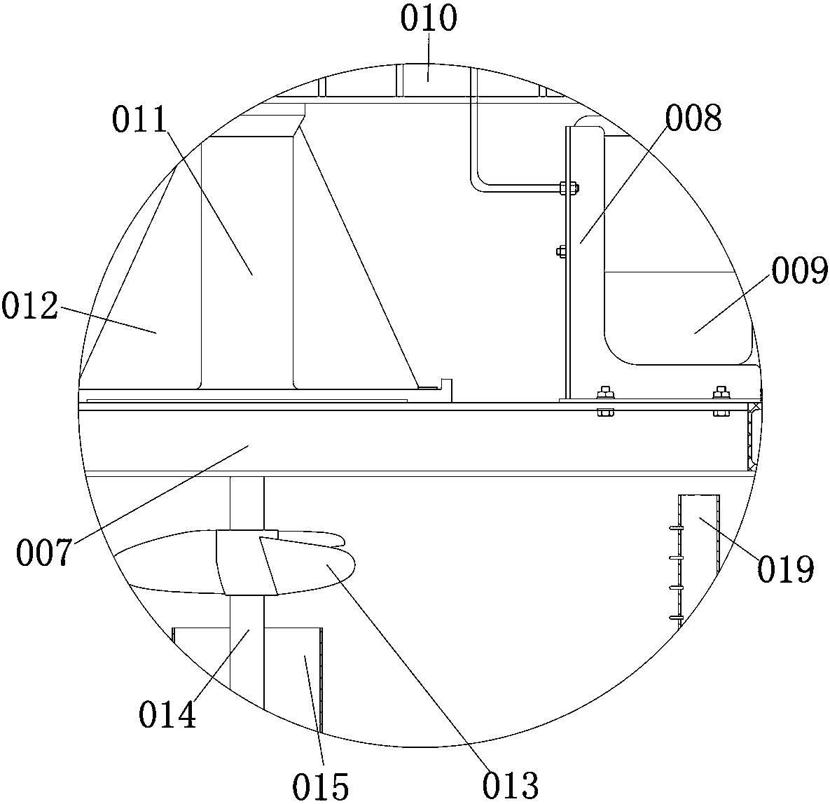
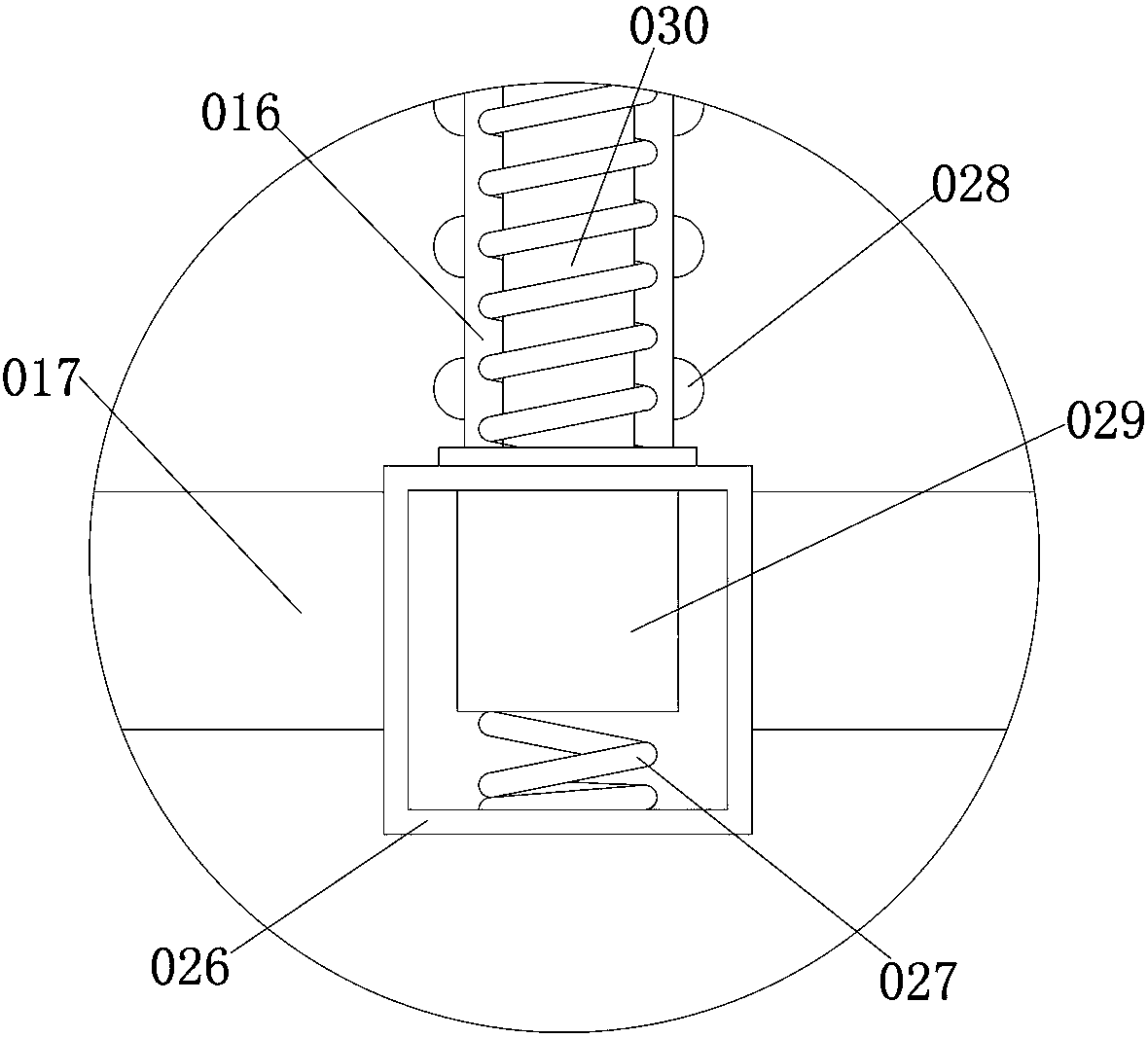
[0020] see Figure 1-3 , the present invention provides a technical solution: a new type of medical device disinfection device, including a leg 001, connected and supporting the bottom plate 005, so that the connection between the disinfection box 006 and the bottom plate 005 is more firm, and the bottom end of the outer wall of the leg 001 is hinged There is a rubber pad 025 to increase the stress area and make the connection between the outrigger 001 and the ...


PUM


Abstract

The invention discloses a novel medical equipment disinfection device. The novel medical equipment disinfection device comprises support legs, wherein the outer wall of each support leg is sleeved with a transverse beam; the inner wall of the transverse beam connected with the outer wall of each support leg in a sleeving way; fixed holes are formed in the outer wall of the transverse beam; the inner wall of each fixed hole is connected with the outer wall of the transverse beam; an inserting block is arranged in the inner wall of each fixed hole; the outer wall of each inserting block is connected with the inner wall of each fixed hole; a bottom plate is welded at the upper surface of each support leg; a disinfection box is hinged to the upper surface of the bottom plate; the lower surfaceof the disinfection box is connected with the upper surface of the bottom plate in a hinge way. The novel medical equipment disinfection device has the advantages that under the cooperation functionof a motor, a belt, a rotary shaft and a rotary rod, and the function of a bracket, the motor is an alternating current servo motor, the power produced by the current of the motor is adjusted, and therotation speed of the motor is adjusted; by adjusting the rotation speed of the motor, the rotation speed of the rotary rod is adjusted; the cleaning efficiency of medical equipment is improved, andthe novel medical equipment disinfection device is suitable for being popularized.

Description

technical field [0001] The invention relates to the technical field of medical instruments, in particular to a novel medical instrument disinfection device. Background technique [0002] In medical diagnosis and treatment, the use of various conventional medical devices is huge, and the disinfection of medical devices is also a very heavy task. The medical device industry involves many industries such as medicine, machinery, electronics, and plastics. It is a multidisciplinary, knowledge-intensive, and capital-intensive high-tech industry. The basic characteristics of high-tech medical equipment are digitization and computerization, which is a multidisciplinary industry. , the crystallization of cross-field modern high-tech, its products have high technical content and high profits, so it is the commanding heights of competition among major scientific and technological countries and large international companies, and the entry threshold is relatively high, even in industries...

Claims


Application Information

Patent Timeline
IPC IPC(8): A61L2/18A61L2/26F26B23/04
CPCA61L2/18A61L2/26A61L2202/24F26B23/04
Inventor 斯琴
Owner DONGGUAN SONGYAN ZHIDA IND DESIGN CO LTD
Why Eureka
Try Eureka