
Vacuum temperature control test chamber

A test box and vacuum technology, which is applied in the direction of laboratory appliances, heating or cooling equipment, shells or chambers, etc., can solve the problems of loss, poor heat exchange effect, inaccurate performance test results, etc., to speed up heat exchange, The effect of enhancing the heat exchange effect

Pending Publication Date: 2018-10-19
重庆哈丁环境试验技术股份有限公司
View PDF8 Cites 0 Cited by
  • Summary
  • Abstract
  • Description
  • Claims
  • Application Information

AI Technical Summary

Problems solved by technology

[0005] However, in a vacuum state, the heat exchange effect in the test chamber is not good, and it is difficult to maintain the ambient temperature required during the product test process, which will lead to inaccurate product performance test results, resulting in unnecessary losses

Method used


Image

  • Vacuum temperature control test chamber
  • Vacuum temperature control test chamber
  • Vacuum temperature control test chamber

Examples


Embodiment 1

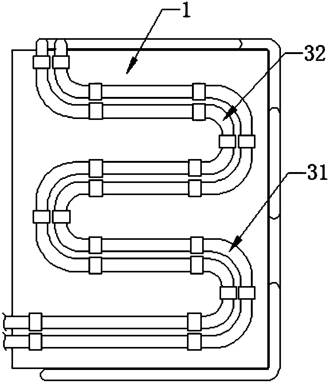
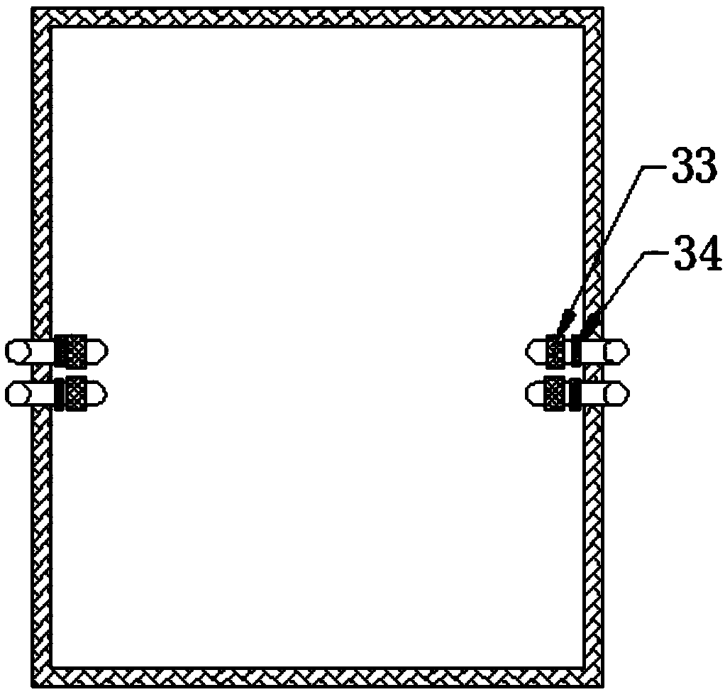
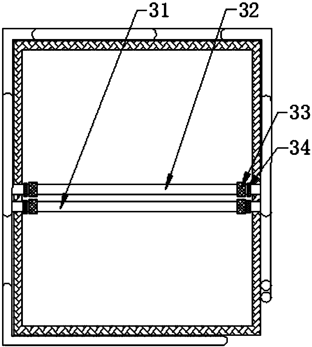
[0047] like figure 1 , Figure 12 As shown, a vacuum temperature control test box includes a temperature control sealing box 1, the temperature control sealing box 1 is connected with a temperature regulating box 2 and an air pressure regulating device, and the box body of the temperature control sealing box 1 is sequentially arranged from inside to outside A box inner shell, an insulating layer 4 and an outer box shell 5 are provided, the key of which is that a door 10 is installed on one side wall of the temperature-controlled sealed box 1, and a peripheral thermostatic tube is arranged in the insulating layer 4 , all of the peripheral thermostatic tubes are closely attached to the box inner shell; the peripheral thermostatic tubes are evenly distributed in an S shape on the box inner shells of the other five box surfaces of the temperature control sealed box 1; The peripheral thermostatic tube is bonded to the inner wall of the temperature-controlled sealed box 1 through ...

Embodiment 2

[0056] Embodiment 2: as image 3 As shown, the built-in thermostatic tube may be a straight tube, and the straight tube connects the third nozzles of the two relative three-way pipes in a straight line;

Embodiment 3

[0057] Embodiment 3: as Figure 4 As shown, the built-in thermostatic tube protrudes toward the top of the temperature-controlled sealed box 1, and the protruding part is close to the top of the temperature-controlled sealed box 1;


PUM


Abstract

The invention relates to a vacuum temperature control test chamber. The vacuum temperature control test chamber comprises a temperature control seal box, the temperature control seal box is connectedwith a temperature adjusting cabinet and an air pressure adjusting device, and a box body of the temperature control seal box is sequentially provided with a box body inner shell, a heat preservationlayer and an outer box shell from inside to outside. The vacuum temperature control test chamber is characterized in that periphery type constant-temperature tubes are arranged in the heat preservation layer, and all the peripheral constant-temperature tubes are tightly attached to the box body inner shell. The vacuum temperature control test chamber has the beneficial effects that (1) the peripheral constant-temperature tubes are arranged in the heat preservation layer and are tightly attached to the temperature control seal box, the heat conductivity of metal is utilized, heat exchange between the periphery type constant-temperature tubes and the interior of the test chamber is accelerated, and therefore the temperature in the test chamber is guaranteed to be constant; and (2) built-in constant-temperature tubes are further arranged inside the temperature control seal box, when a product for testing is relatively small, the peripheral constant-temperature tubes and the built-in constant-temperature tubes can be combined, and therefore the heat exchange effect of the constant-temperature tubes and the test chamber is obviously enhanced.

Description

technical field [0001] The invention relates to the field of product performance testing, in particular to a vacuum temperature control test chamber. Background technique [0002] When a product is produced, in order to improve the reliability of the product, reliability tests will be carried out to expose the weak links of the product. Through the analysis of the cause of failure and failure mode, it provides a theoretical basis for the improvement and optimization design of the product in the later stage. [0003] The traditional reliability test is to test whether the product can complete the specified function under the specified conditions and within the specified time. However, the current market requirement for products is to be able to meet any requirements put forward by users at any time, which cannot be met by traditional reliability experiments. Therefore, there has been a reliability enhancement test. The reliability enhancement test is to impose a single or c...

Claims


Application Information

Patent Timeline
IPC IPC(8): B01L1/00B01L7/00
CPCB01L1/00B01L7/00
Inventor 龙德中雷正根
Owner 重庆哈丁环境试验技术股份有限公司
Learn More