Gas cooling apparatus

A gas cooling and gas pipeline technology, which is used in charging systems, exhaust gas recirculation, lighting and heating equipment, etc., can solve the problems of insufficient thin boundary layer, large space, and insufficient heat transfer on the heat transfer surface.

Inactive Publication Date: 2005-02-02
USUI CO LTD
View PDF4 Cites 15 Cited by
  • Summary
  • Abstract
  • Description
  • Claims
  • Application Information

AI Technical Summary

Problems solved by technology

[0006] However, in the conventional double-tube type heat exchangers disclosed in JP-A-11-23181, JP-A-2002-350071, JP-A-2000-111277 and JP-A-2003-21478, the EGR gas flow passage is defined The pipes in many cases have a smooth inner peripheral surface over the entire length, which leads to the problem of insufficient heat transfer near the center of the pipe, resulting in a lower EGR gas cooling efficiency
[0007] Moreover, in the EGR gas cooling devices disclosed in JP-A-9-88730 and JP-A-9-88731, there are advantages of easy processing and low cost, but due to a small heat transfer area, it is necessary to specially increase Its axial length to ensure its heat transfer performance, so that when it is installed on a car, the cooling device will occupy a large space, which is problematic in design, and will further produce such One problem is that since the gas flows along the EGR gas duct, there will be little turbulence formed in the gas flow, so that the boundary layer on the heat transfer surface is not thin enough and the heat transfer performance will be poor

Method used


Image

  • Gas cooling apparatus
  • Gas cooling apparatus
  • Gas cooling apparatus

Examples


Embodiment Construction

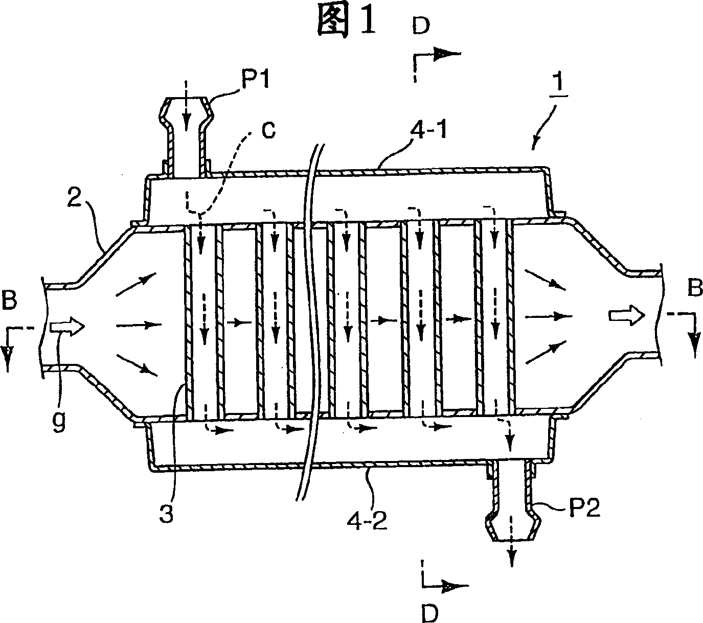
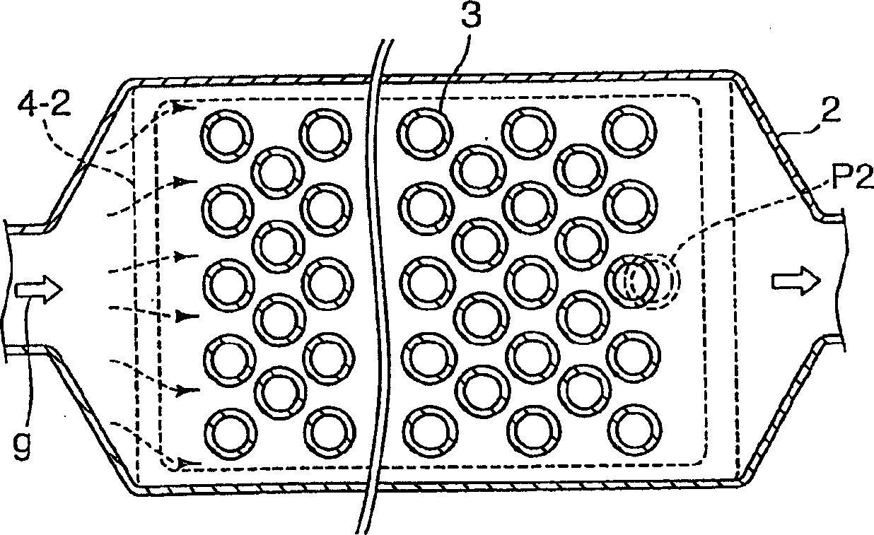
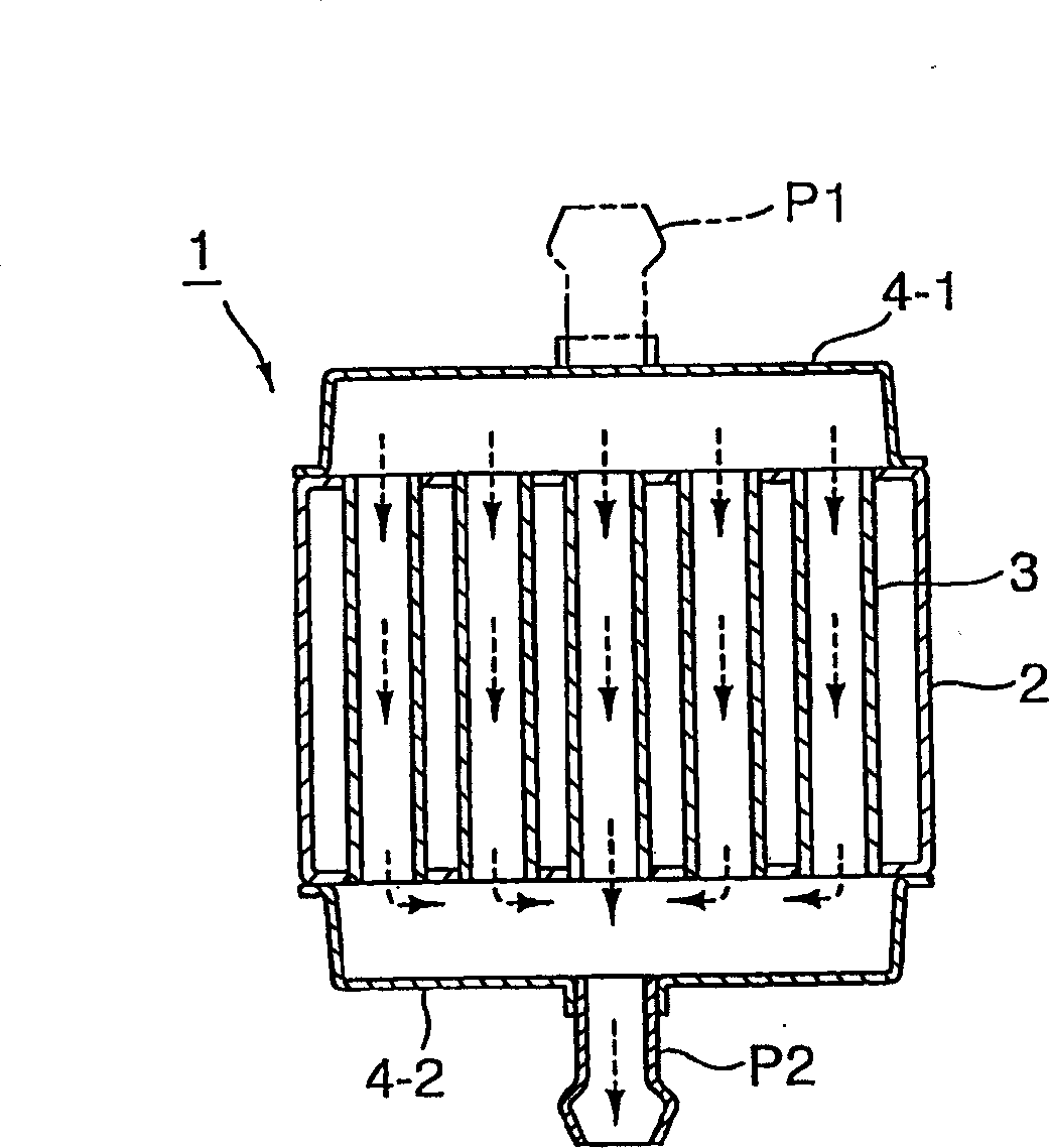
[0031] First of all, in the present invention, the EGR gas cooling device 1 shown in FIGS. Vertically intersecting, the diameter of the EGR gas pipe is relatively large and has a rectangular cross-section, the cooling pipe is fixedly installed on the EGR gas pipe at predetermined intervals, so as to extend through the outer peripheral wall of the EGR gas pipe, and each cooling pipe Both ends are open outwards. Further, cooling jackets 4-1, 4-2 are fixed to the outer peripheral surface of the EGR gas duct at both ends in the axial direction of the cooling duct. The cooling jackets 4-1, 4-2 are respectively provided with a cooling medium inflow hole P1 and an outflow hole P2.

[0032] In the EGR gas cooling device constructed in the above manner, the EGR gas flowing in the direction of the arrow g in the EGR gas pipe 2 is cooled by the cooling medium which comes from the cooling jacket 4-1 and passes through each cooling pipe. 3. Flow in the direction of arrow c. Simultaneous...


PUM


Abstract

A gas cooling device capable of efficiently cooling a gas such as an EGR gas, etc. is provided. A multiplicity of cooling pipes perpendicularly intersecting a gas flow direction in a gas pipe for a gas such as an EGR gas, etc. are provided to extend through an outer peripheral wall of the gas pipe, a cooling jacket is provided on an outer surface of the gas pipe on both sides of a group of the cooling medium pipes in an axial direction, or on the entire outer surface of the gas pipe, and the gas in the gas pipe is cooled by a cooling medium flowing through the cooling pipes.

Description

technical field [0001] The present invention relates to a gas cooling device, in particular to a device for cooling EGR gas in an EGR gas pipeline during exhaust gas circulation (hereinafter referred to as EGR), in which a part of exhaust gas is extracted from the exhaust system of a diesel engine away, and through the EGR gas duct back into the intake system to be added to a mixture. Background technique [0002] The method of taking a part of the exhaust gas from the exhaust system and returning it to the intake system of the engine to add the exhaust gas to a mixture is called EGR (Exhaust Gas Recirculation). EGR is considered to be an effective method in purifying engine exhaust gas and improving thermal efficiency because it can produce many beneficial effects, such as suppressing NO x (Nitrogen oxides) generation, reduced pumping losses, reduced heat loss to the coolant, which is often accompanied by a drop in combustion gas temperature, increased specific heat absorp...

Claims


Application Information

Patent Timeline
Patent Type & Authority Applications(China)
IPC IPC(8): F28D7/16F02M25/07
CPCF28D7/1615F28D21/0003F28D7/1653F02M26/32
Inventor 后藤忠弘
Owner USUI CO LTD
Why Eureka
Try Eureka