Cutting and milling mechanism of automatic machining equipment of wire stripping blade and control method of cutting and milling mechanism

An automatic processing, cutting and milling technology, applied in metal processing equipment, metal processing, milling machine equipment and other directions, can solve the problem of delaying production efficiency and achieve the effect of improving production efficiency

Active Publication Date: 2018-10-19
台州孚亚电机有限公司
View PDF27 Cites 1 Cited by
  • Summary
  • Abstract
  • Description
  • Claims
  • Application Information

AI Technical Summary

Problems solved by technology

[0003] At present, many wire strippers adopt an assembled structure, that is, the wire stripping blade is processed in advance, and then the wire stripping blade is assembled on the pliers, so that there is no need to cut and mill the pliers themselves. During the production process of the wire stripping blade, all The width of the stripping groove is gradually increasing, so milling cutters of different specifications need to be used, and the replacement of milling cutters requires the equipment to be shut down, thereby delaying production efficiency, so it is necessary to design a more convenient cutting and milling equipment

Method used


Image

  • Cutting and milling mechanism of automatic machining equipment of wire stripping blade and control method of cutting and milling mechanism
  • Cutting and milling mechanism of automatic machining equipment of wire stripping blade and control method of cutting and milling mechanism
  • Cutting and milling mechanism of automatic machining equipment of wire stripping blade and control method of cutting and milling mechanism

Examples


Embodiment Construction

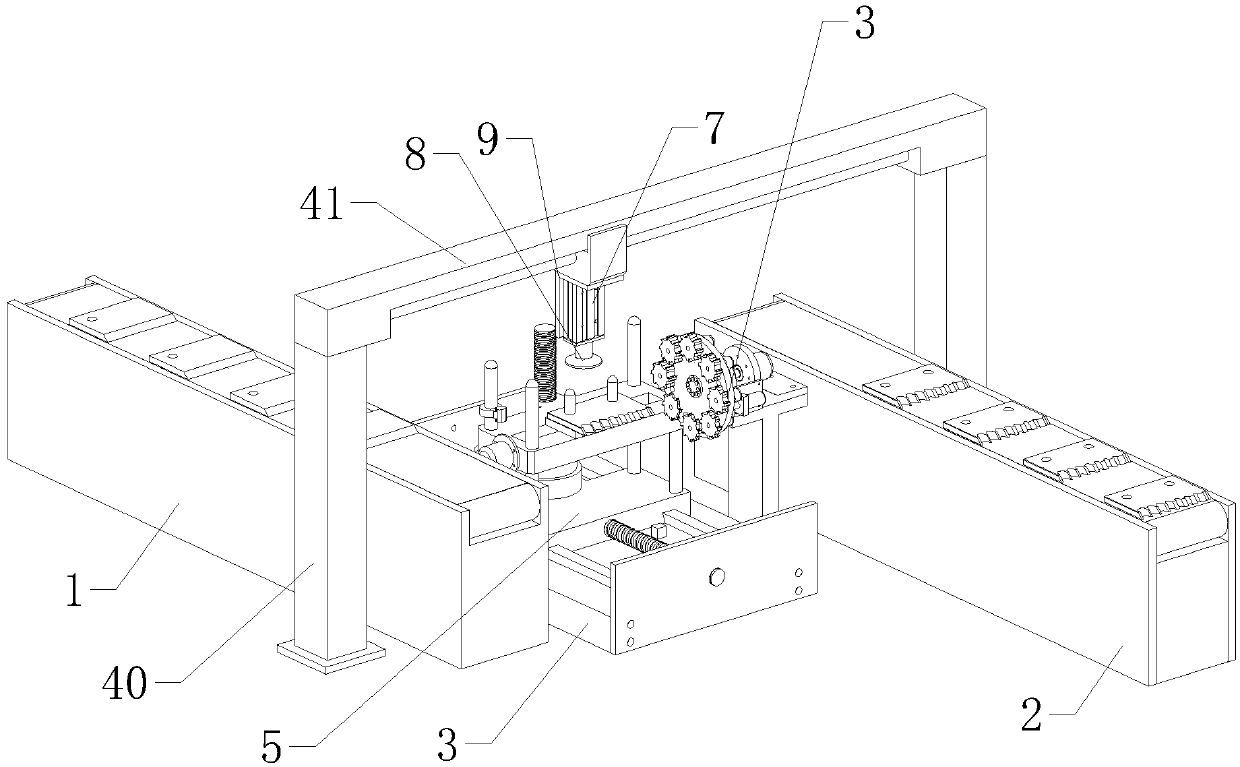
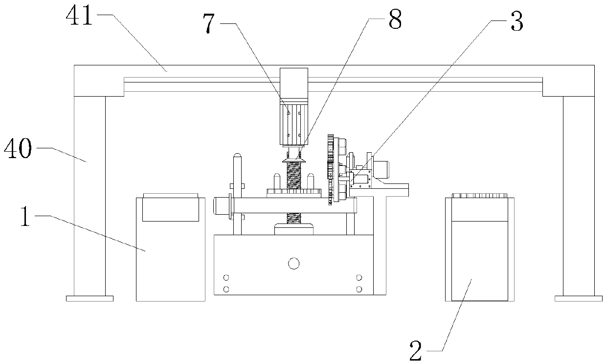
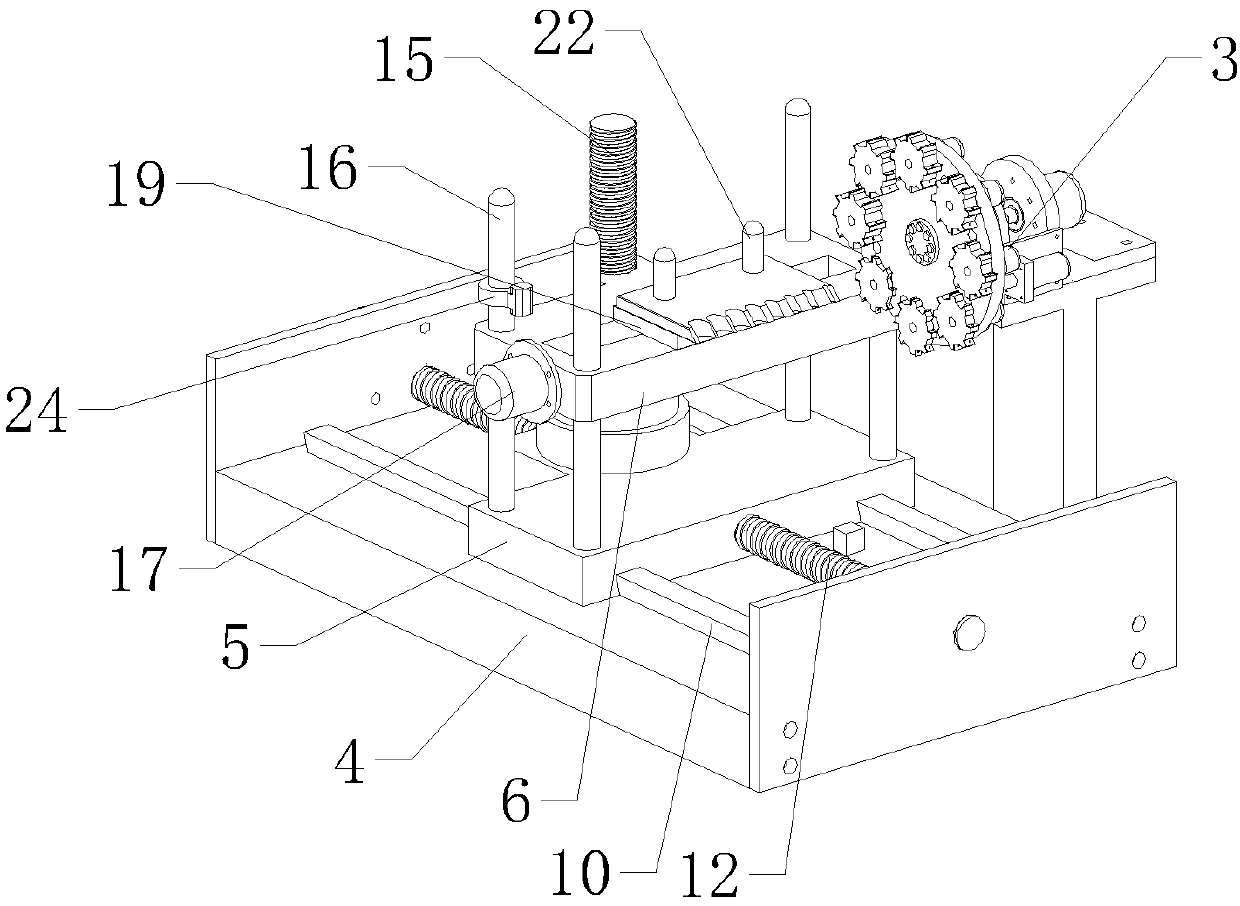
[0032] Below in conjunction with the accompanying drawings and embodiments of the description, the specific embodiments of the present invention are described in further detail:

[0033] refer to Figure 1 to Figure 11 The shown automatic processing equipment for stripping blades includes an original conveyor belt 1, a finished product conveyor belt 2, a material moving mechanism, a positioning mechanism, a three-axis speed regulating mechanism and a cutting and milling mechanism 3. The original conveyor belt 1 and the finished product conveyor belt 2 are arranged parallel to each other. , the material moving mechanism is set directly above the original conveyor belt 1 and the finished product conveyor belt 2, the positioning mechanism is set on the top of the three-axis speed regulating mechanism, and the cutting and milling mechanism 3 is set on the side of the three-axis speed regulating mechanism. When the original is cut, the three-axis speed regulating mechanism and the ...


PUM


Abstract

The invention relates to the field of automatic machining, in particular to a control method of a cutting and milling mechanism of automatic machining equipment of a wire stripping blade. A mounting base, a rotating switching assembly and a locking assembly are included. The rotating switching assembly comprises a rotary motor, a rotating disc and eight milling cutters of different specifications.The rotating disc is vertically arranged on the side, away from the rotary motor, of a supporting frame. The center of the rotating disc is fixedly connected with an output shaft of the rotary motor.The eight milling cutters are evenly distributed on the edge of the side, away from the rotary motor, of the rotating disc. Eight cutting and milling motors are arranged on the side, close to the rotary motor, of the rotating disc and are fixedly connected with the eight milling cutters in one-to-one correspondence. The locking assembly locks the rotating disc through lock holes in the rotating disc. According to the cutting and milling mechanism of the automatic machining equipment of the wire stripping blade, wire stripping grooves of different specifications can be automatically cut and milled out, the trouble of replacing the milling cutters by shutdown is omitted, and the production efficiency is improved.

Description

technical field [0001] The invention relates to the field of automatic processing, in particular to a cutting and milling mechanism of an automatic processing equipment of a wire stripping blade and a control method thereof. Background technique [0002] The wire stripper is one of the tools commonly used by electricians, motor repairers, and instrumentation electricians. It is used for power workers to strip the surface insulation of the wire head. Wire strippers can separate the insulation of the wire from the wire, and can also prevent electric shock. A milling cutter is a rotary cutter with one or more teeth for milling. When working, each cutter tooth cuts off the allowance of the workpiece intermittently in turn. Milling cutters are mainly used to process planes, steps, grooves, forming surfaces and cutting workpieces on milling machines. There are two ways of milling relative to the feed direction of the workpiece and the rotation direction of the milling cutter: the...

Claims


Application Information

Patent Timeline
Patent Type & Authority Applications(China)
IPC IPC(8): B23C3/30B23C9/00B23Q7/00B23Q7/04
CPCB23C3/305B23C9/00B23Q7/00B23Q7/04
Inventor 夏文斌
Owner 台州孚亚电机有限公司
Why Eureka
Try Eureka