Motion mechanism for shifting fork shaft of double-power drive system

A technology of dual power drive and motion mechanism, applied in the directions of transportation and packaging, control devices, vehicle components, etc., can solve the problems of shifting delay, easy jamming of the fork shaft, etc. smooth effect

Pending Publication Date: 2018-10-19
WUXI ZHENGRUI AUTOMOBILE TRANSMISSION TECH CO LTD
View PDF0 Cites 0 Cited by
  • Summary
  • Abstract
  • Description
  • Claims
  • Application Information

AI Technical Summary

Problems solved by technology

[0003] The purpose of the present invention is to provide a kinematic mechanism for the shift fork shaft of the dual power drive system, which has the advantages of fast movement and precise position pointing, and solves the problem that the movement of the shift fork shaft is prone to jamming and causes gear shift lag

Method used


Image

  • Motion mechanism for shifting fork shaft of double-power drive system
  • Motion mechanism for shifting fork shaft of double-power drive system

Examples


Embodiment Construction

[0016] The following will clearly and completely describe the technical solutions in the embodiments of the present invention with reference to the accompanying drawings in the embodiments of the present invention. Obviously, the described embodiments are only some, not all, embodiments of the present invention. Based on the embodiments of the present invention, all other embodiments obtained by persons of ordinary skill in the art without making creative efforts belong to the protection scope of the present invention.

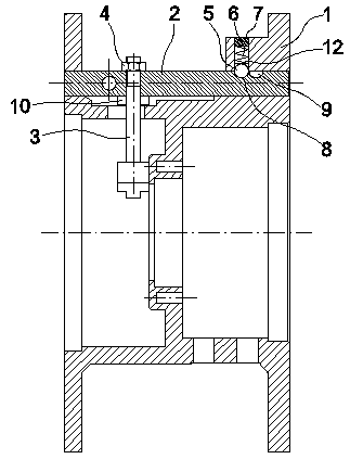
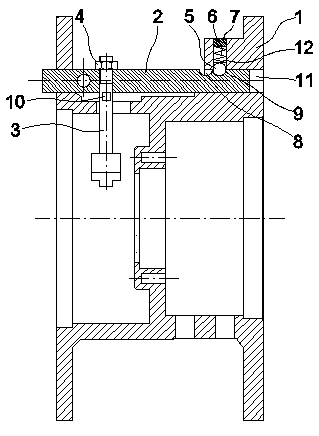
[0017] see figure 1 and figure 2 , a kinematic mechanism for a shift fork shaft of a dual-power drive system, comprising a housing 1 and a shift fork shaft 2, the housing 1 is in a hollow ring structure, and its left and right ends are ring surfaces with a large diameter. A coaxial axial through hole 11 is provided on the outer side of the annular surface at the left and right ends of the annular surface in the middle of the housing 1, and a shift fork shaft...


PUM


Abstract

The invention discloses a motion mechanism for a shifting fork shaft of a double-power drive system. The motion mechanism for the shifting fork shaft of the double-power drive system comprises a shelland a shifting fork shaft; the shell is of a hollow circular ring-shaped structure; the left and right ends of the shell are circular ring surfaces with larger diameters; axial through holes which are coaxial are arranged in positions, on the external side of a circular ring surface in the middle of the shell, on the circular ring surfaces at the left and right ends of the shell; the shifting fork shaft capable of axially moving is arranged in the axial through hole; a separating groove and a jointing groove with adjacent positions are formed in the upper surface of the shifting fork shaft; aradial through hole communicating with the axial through holes is formed in the right side circular ring surface of the shell; and a limiting mechanism for accurately enabling the shifting fork shaftto be in a separating position or a jointing position is arranged in the radial through hole. According to the motion mechanism for the shifting fork shaft of the double-power drive system, by forming the axle through holes which are coaxial in the circular ring surfaces at the left and right ends of the shell and arranging the shifting fork shaft in the axial through hole, the axial moving stability of the shifting fork shaft is enhanced so that the impact caused by separating or jointing of shifting forks is reduced and the stable and reliable motion of the shifting fork shaft is guaranteed; and the motion mechanism for the shifting fork shaft of the double-power drive system has obvious use effect and is worthy of being popularized.

Description

technical field [0001] The invention relates to the technical field of dual-power separation and jointing of automobiles, in particular to a movement mechanism for a shift fork shaft of a dual-power drive system. Background technique [0002] In the field of automobile dual power separation and joint technology, shift forks are commonly used to realize the joining and separation of oppositely installed power shafts; and the part that drives the movement of the shift fork is the shift fork shaft. At present, the movement of the shift fork shaft is prone to jamming, resulting in Shifting hysteresis affects the smoothness of the movement of the shift fork shaft and the accuracy of position orientation, which in turn affects the reliability of shifting or clutching. Contents of the invention [0003] The purpose of the present invention is to provide a kinematic mechanism for a shift fork shaft of a dual-power drive system, which has the advantages of fast movement and precise...

Claims


Application Information

Patent Timeline
Patent Type & Authority Applications(China)
IPC IPC(8): B60K23/00
CPCB60K23/00
Inventor 张国伟谢嘉栋陈国强
Owner WUXI ZHENGRUI AUTOMOBILE TRANSMISSION TECH CO LTD
Why Eureka
Try Eureka