Single auxiliary elevator self-locking bolt

An elevator and self-locking technology, applied in the direction of load hanging components, transportation and packaging, can solve the problem of unsafe bolt loosening, and achieve the effects of simple structure, high reliability and safety, and convenient and fast operation.

Pending Publication Date: 2018-10-19
江苏如东联丰石油机械有限公司
View PDF0 Cites 2 Cited by
  • Summary
  • Abstract
  • Description
  • Claims
  • Application Information

AI Technical Summary

Problems solved by technology

[0003] In order to solve the above technical problems, the present invention provides a single auxiliary elevator self-locking latch, which can avoid the unsafe problem of the latch being loose

Method used


Image

  • Single auxiliary elevator self-locking bolt
  • Single auxiliary elevator self-locking bolt
  • Single auxiliary elevator self-locking bolt

Examples


Embodiment 1

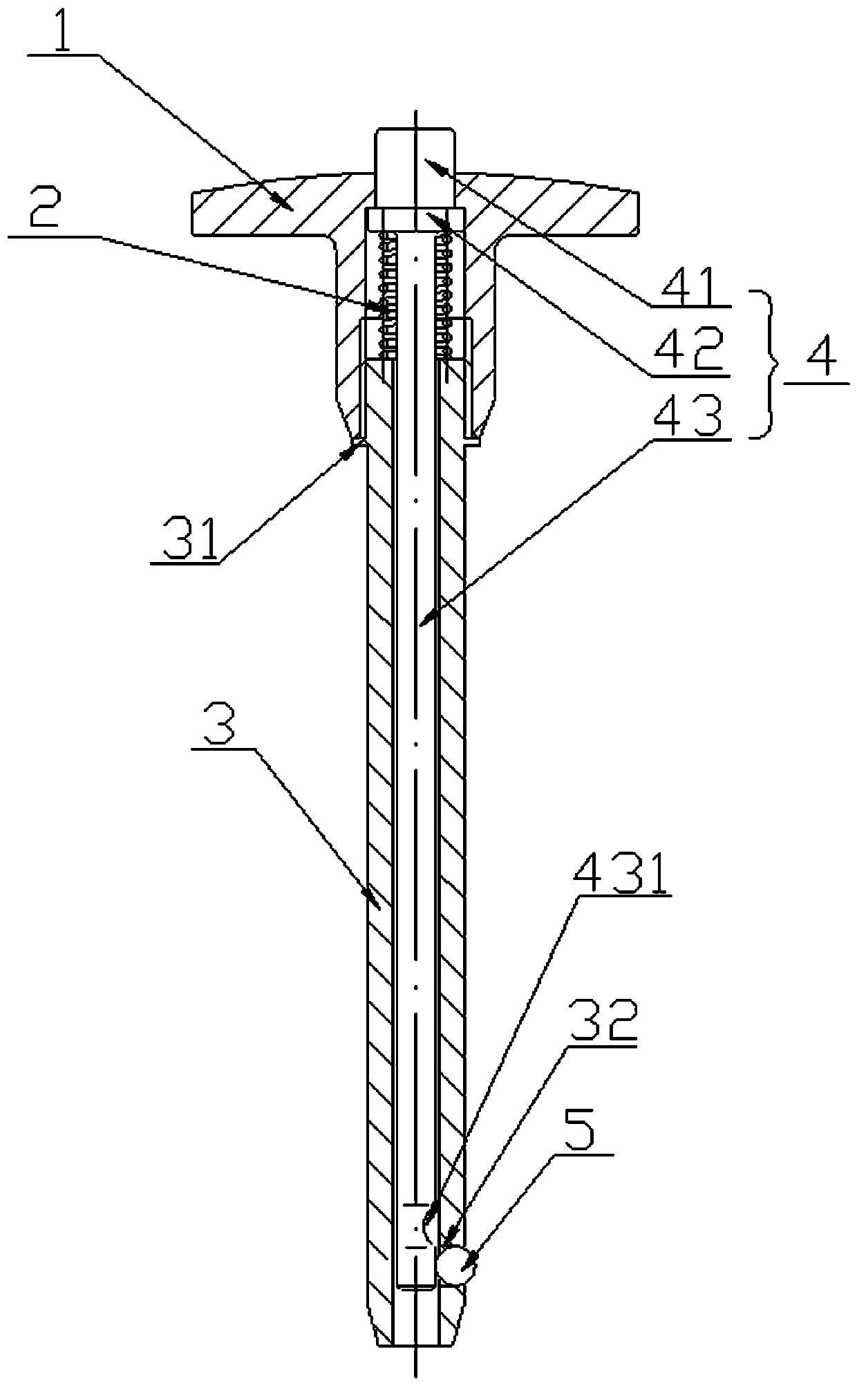
[0021] Such as figure 1 As shown, a single auxiliary elevator self-locking bolt includes a handle 1, a spring 2, a threaded pin 3, a lower pressure rod 4 and a steel ball 5, a snap ring 31 is arranged on the outside of the threaded pin 3 above, and the threaded pin 3 The lower end is provided with a ball position through hole 32 at one side, and the lower pressing rod 4 includes a hand pressing part 41, a limiting part 42 and a main rod part 43 from top to bottom, and the lower end of the main rod part 43 is arranged on one side. There is a steel ball slot 431, the steel ball 5 is placed in the ball position through hole 32, the lower pressure rod 4 is placed in the threaded pin 3, the spring 2 is set outside the top of the main rod part 43 of the lower pressure rod 4, and is located on the threaded pin 3 and the limit portion 42 of the lower pressure rod 4, the handle 1 is clamped outside the threaded pin 3 and fixed together by threaded connection, and the bottom end of the...

Embodiment 2

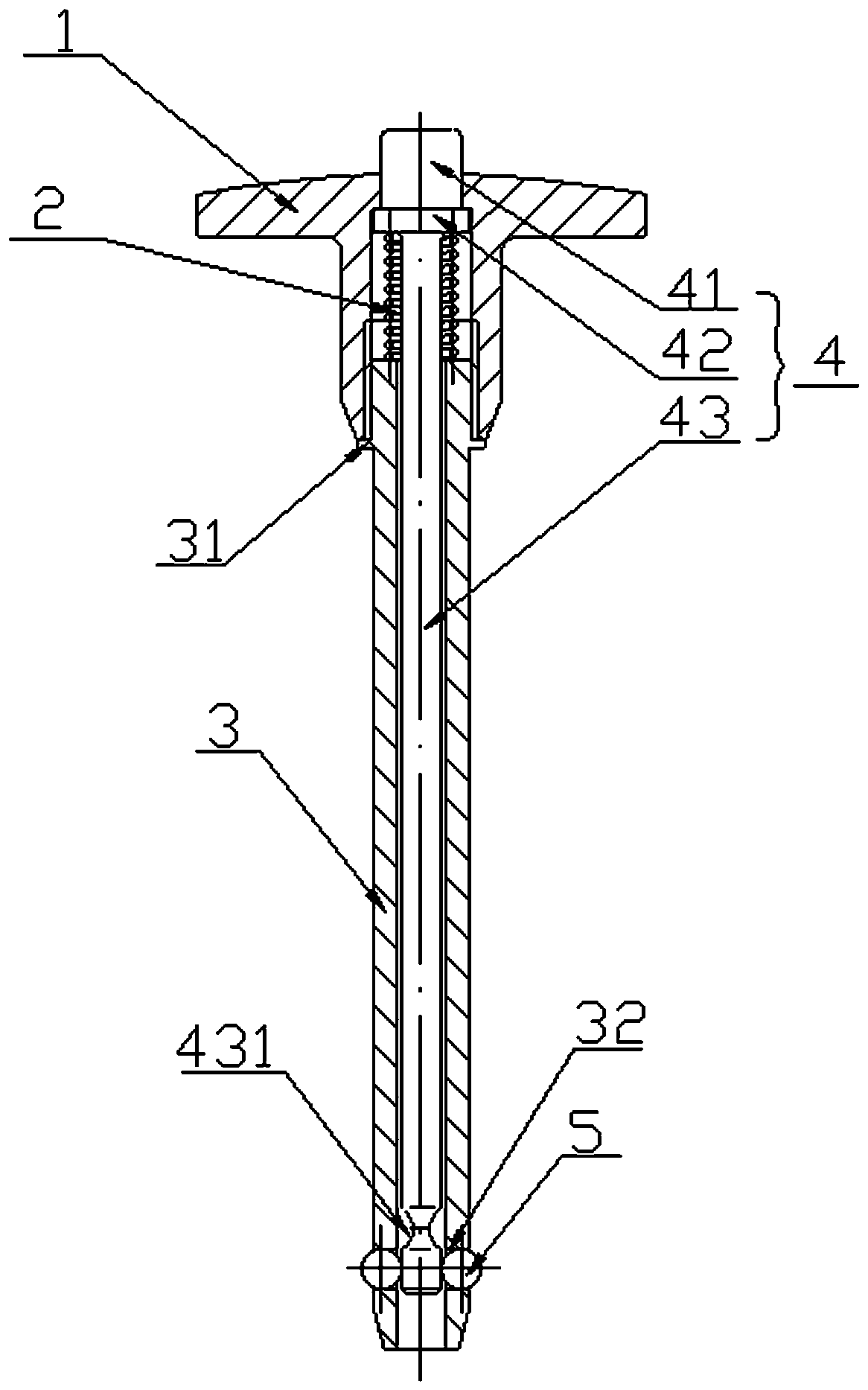
[0023] Such as figure 2 As shown, a single auxiliary elevator self-locking bolt includes a handle 1, a spring 2, a threaded pin 3, a lower pressure rod 4 and two steel balls 5, a snap ring 31 is arranged on the outside of the threaded pin 3 above, and the threaded pin 3 The lower end is provided with two opposite ball position through holes 32 at the positions on both sides. The lower pressing rod 4 includes a hand pressing part 41, a limiting part 42 and a main rod part 43 in order from top to bottom. The lower end of the main rod part 43 is located at There are two opposite steel ball slots 431 on both sides, the two steel balls 5 are respectively placed in the two ball position through holes 32, the lower pressing rod 4 is placed in the threaded pin 3, and the spring 2 is set on the lower pressing rod 4 outside the top of the main rod part 43, between the threaded pin 3 and the limit part 42 of the lower pressure rod 4, the handle 1 is clamped outside the threaded pin 3, f...


PUM


Abstract

The invention discloses a single auxiliary elevator self-locking bolt. The bolt comprises a hand shank, a spring, a threaded pin, a lower pressing rod and a steel ball, a clamping ring is arranged onthe outer side of the threaded pin, a ball position through hole is formed in the position of the lower end of the threaded pin, the lower pressing rod sequentially comprises a hand pressing part, a limiting part and a main rod part from top to bottom, a steel ball clamping groove is formed in the position, located at the lower end, of the main rod part, the steel ball is placed in the ball position through hole, the lower pressing rod is arranged in the threaded pin, the spring sleeves are placed on the top end of the main rod part of the lower pressing rod, a handle is clamped outside the threaded pin, connecting and fixing together through threaded connection, and the bottom end of the handle abuts against the upper end of the clamping ring on the outer side of the threaded pin. The bolt has the advantages that the pull pin or the plug pin can be pulled down by pressing down the pressing rod, self-locking can be realized by loosening the lower pressing rod, convenient and rapid to operate, high in reliability and safety, simple in structure, convenient to assemble, low in manufacturing cost and capable of being popularized and used.

Description

technical field [0001] The invention relates to the field of self-locking latch devices, in particular to a single auxiliary elevator self-locking latch. Background technique [0002] In the process of oil drilling, a single auxiliary elevator is often used, such as Figure 4 As shown, a single auxiliary elevator usually uses a split pin to realize the locking function. The cooperation between the split pin and the hole is a clearance fit. security risks. Contents of the invention [0003] In order to solve the above technical problems, the present invention provides a single auxiliary elevator self-locking latch, which can avoid the unsafe problem of the latch being loose. [0004] The technical scheme adopted in the present invention is: [0005] A single auxiliary elevator self-locking bolt, including a handle, a spring, a threaded pin, a lower pressing rod and a steel ball; [0006] The outside of the threaded pin is provided with a snap ring above, and the threaded...

Claims


Application Information

Patent Timeline
Patent Type & Authority Applications(China)
IPC IPC(8): B66C1/22
CPCB66C1/22
Inventor 王展鹏王钦峰
Owner 江苏如东联丰石油机械有限公司
Why Eureka
Try Eureka