
Handling outlet structure of fingerprint reader for electronic lock

A fingerprint reader and electronic lock technology, which is applied in the field of electronic locks, can solve problems such as wire bending, wire breaking, and scratching inside the panel, achieving stable structure, good protection, and reducing unstable factors.

Pending Publication Date: 2018-10-19
NANJING IOT SENSOR TECH
View PDF0 Cites 5 Cited by
  • Summary
  • Abstract
  • Description
  • Claims
  • Application Information

AI Technical Summary

Problems solved by technology

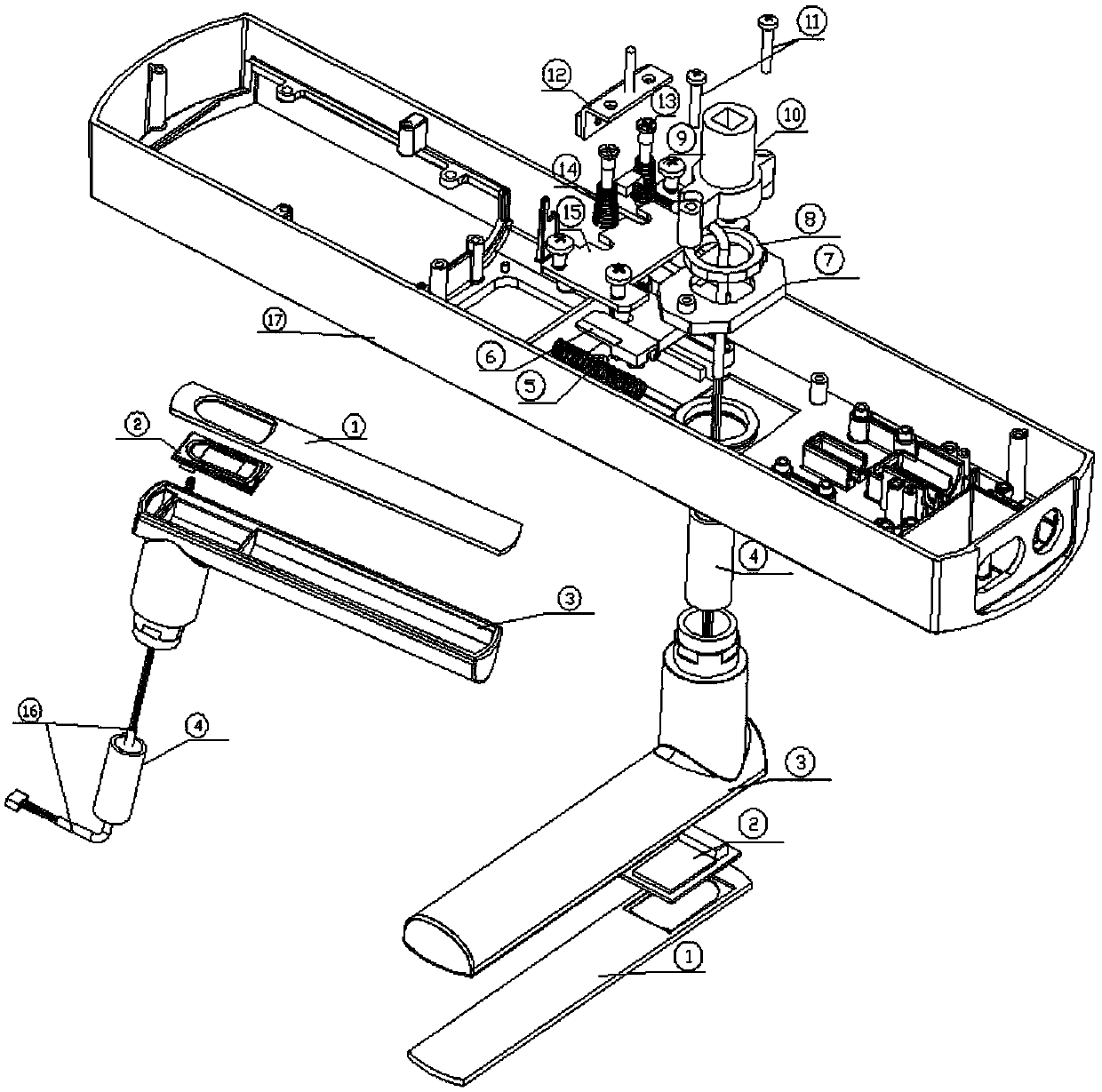
[0004] The purpose of the present invention is to solve the unpredictable problems caused by placing the fingerprint reader on the handle in the prior art, and the wire rod swings with the handle to cause bending, and it is easy to break the wire rod and scrape the inside of the panel for a long time. The problem of risk, and the handle outlet structure of the fingerprint reader for the electronic lock proposed

Method used


Image

  • Handling outlet structure of fingerprint reader for electronic lock
  • Handling outlet structure of fingerprint reader for electronic lock
  • Handling outlet structure of fingerprint reader for electronic lock

Examples


Embodiment Construction

[0020] The following will clearly and completely describe the technical solutions in the embodiments of the present invention with reference to the accompanying drawings in the embodiments of the present invention. Obviously, the described embodiments are only some, not all, embodiments of the present invention.

[0021] In describing the present invention, it should be understood that the terms "upper", "lower", "front", "rear", "left", "right", "top", "bottom", "inner", " The orientation or positional relationship indicated by "outside", etc. is based on the orientation or positional relationship shown in the drawings, and is only for the convenience of describing the present invention and simplifying the description, rather than indicating or implying that the referred device or element must have a specific orientation, so as to Specific orientation configurations and operations, therefore, are not to be construed as limitations on the invention.

[0022] refer to Figure ...


PUM


Abstract

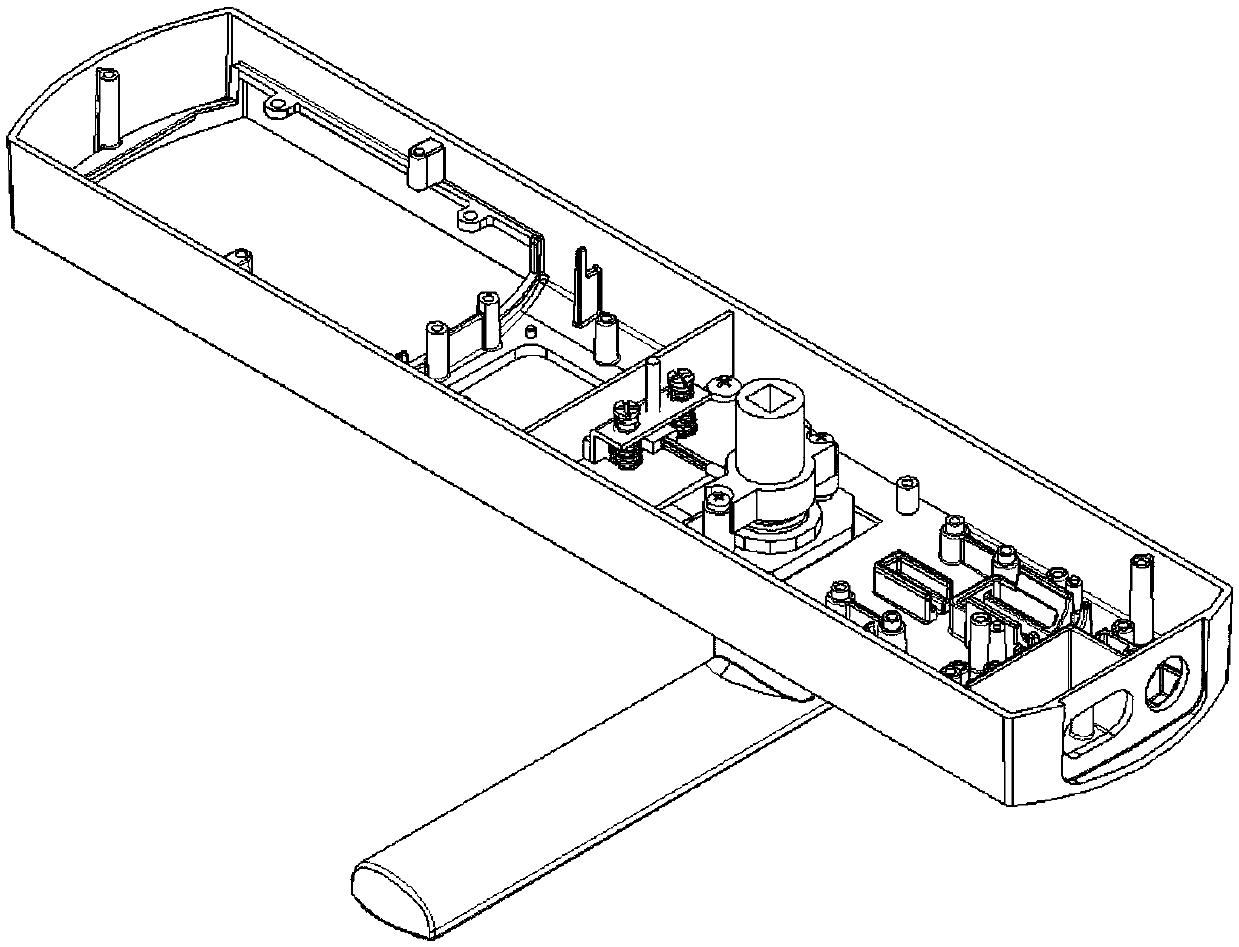
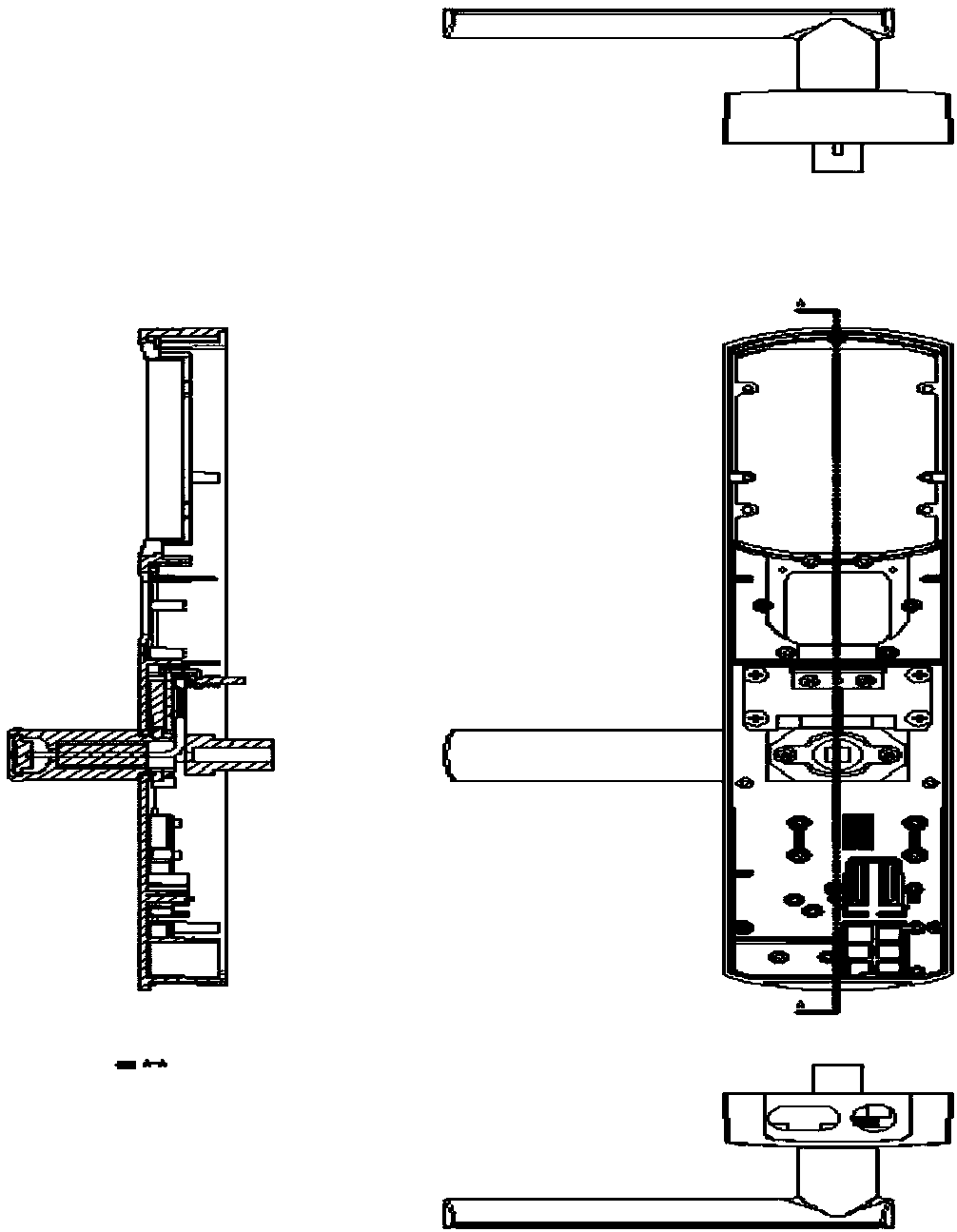
The invention discloses a handling outlet structure of a fingerprint reader for an electronic lock. The handling outlet structure comprises a panel, a mounting hole is formed in one side of the panel,the mounting hole is internally provided with a handling module, and a reset tumbler is arranged on the side, away from the handling module, of the panel and arranged on the handling module in a sleeving mode. A sliding groove is formed in the other side of the panel and located on one side of the mounting hole. A pushing plate module is arranged in the sliding groove, a limiting module is arranged above the pushing plate module, the handling module is connected with the limiting module, and a clutch module is arranged at the upper end of the reset tumbler. The handling outlet structure is stable in structure, simple in operation, scientific and reasonable in design and short in production cycle, an electronic lever handle can quickly turn left and right, and the operating difficulty of an installing master or a client is reduced; and the unstable factors caused by reversing the lever handle by unscrewing screws are reduced, and the fingerprint line can be better protected.

Description

technical field [0001] The invention relates to the technical field of electronic locks, in particular to a handle outlet structure for a fingerprint reader of an electronic lock. Background technique [0002] In the current electronic lock market, in order to provide customers with a better operating experience when opening the door, many manufacturers often place the fingerprint reader on the handle. Although they do so to improve the customer's experience of opening the door, However, when they design the fingerprint reader's fingerprint line to connect to the MCU main board, they generally swing with the handle and the handle reset arm. The fingerprint line will always be bent, so the fingerprint line There will often be a situation where a certain connecting line is broken, and the internal structure of the panel cannot completely avoid the area where the fingerprint line swings and when the handle is opened left and right to change the direction, the fingerprint line w...

Claims


Application Information

Patent Timeline
Patent Type & Authority Applications(China)
IPC IPC(8): E05B3/00E05B9/00E05B63/04
CPCE05B3/00E05B9/002E05B63/04
Inventor 梁泉朱俊岗朱峰朱俊岭余建美
Owner NANJING IOT SENSOR TECH
Learn More