
Controllable oil drain device

An oil drain and drain hole technology, which is used in wellbore/well components, earthmoving, sealing/packaging, etc. Diameter and other issues, to achieve the effect of not changing the strength, opening reliably, and increasing the clearance volume

Pending Publication Date: 2018-10-19
TOP WELL PETROLEUM TECH COMPANY
View PDF0 Cites 1 Cited by
  • Summary
  • Abstract
  • Description
  • Claims
  • Application Information

AI Technical Summary

Problems solved by technology

[0003] At present, percussion type oil drainer and reciprocating oil drainer are commonly used, including friction type oil drainer, holding pressure open type, etc., due to the influence of condensate oil, wax deposition, pipe string strength and pipe string internal scale , it is difficult to open the oil drainer, some oil drainers change the structure of the pipe string, such as the percussion type oil drainer increases the clearance volume of the reciprocating oil pump, the reciprocating oil drain pump is easy to open, and the diameter of the pipe string shrinks, etc.

Method used


Image

  • Controllable oil drain device
  • Controllable oil drain device

Examples


Embodiment Construction

[0017] The technical solutions of the present invention will be further described below through specific examples.

[0018] The present invention will now be described more fully with reference to the accompanying drawings, in which exemplary embodiments of the invention are shown. This invention may, however, be embodied in many different forms and should not be construed as limited to the exemplary embodiments set forth herein. Rather, these embodiments are provided so that this disclosure will be thorough and complete, and will fully convey the scope of the invention to those skilled in the art.

[0019] For ease of description, spatially relative terms such as "upper," "lower," "left," and "right" may be used herein to describe the relationship of one element or feature relative to another element or feature shown in the figures. It will be understood that the spatial terms are intended to encompass different orientations of the device in use or operation in addition to t...


PUM


Abstract

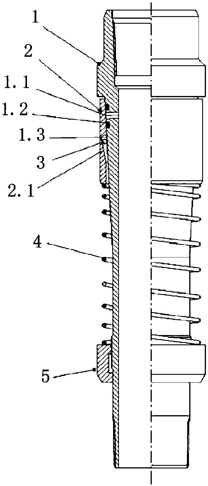
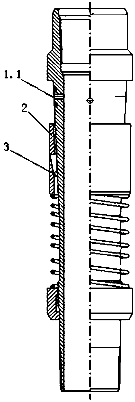
The invention provides a controllable oil drain device. The controllable oil drain device comprises a main body prepared from a non-magnetic material, wherein a seal sleeve, a spring and a regulatingring are arranged on the main body sequentially; a discharge hole in the outer bevel of the main body is sealed by the inner bevel of the seal sleeve, and the spring is arranged between the regulatingring and the seal sleeve; a lock ball is arranged in a lock ball groove in the seal sleeve. The controllable oil drain device has the beneficial effects that inner drift diameter of a tubing string is not changed, clearance volume is not increased, strength of the tubing string is not changed, the oil drain device can be opened only by feeding a strongly magnetic weight bar into the tube string,and the oil drain device is opened reliably.

Description

technical field [0001] The invention relates to the technical field of supporting tools for oil recovery and workover in oil fields, and more specifically relates to a controllable oil drainer. Background technique [0002] The oil drainer is the most commonly used supporting tool on the oil production string. Its function is to drain the oil-water mixture in the string before the string is lifted during the maintenance of the string, so as to prevent the oil and water from polluting the well site ground during the lifting process. Improving the working conditions of workers; [0003] At present, percussion type oil drainer and reciprocating oil drainer are commonly used, including friction type oil drainer, holding pressure open type, etc., due to the influence of condensate oil, wax deposition, pipe string strength and pipe string internal scale , It is difficult to open the oil drainer, some oil drainers have changed the structure of the pipe string, such as the percussi...

Claims


Application Information

Patent Timeline
Patent Type & Authority Applications(China)
IPC IPC(8): E21B34/14
CPCE21B34/14
Inventor 姚小杰李岸然兰卫家房新扬
Owner TOP WELL PETROLEUM TECH COMPANY
Learn More