Transformer overload calculation method and system and terminal equipment
A calculation method and transformer technology, applied in the field of transformers to reduce participation, reduce personnel input costs, and improve work efficiency
- Summary
- Abstract
- Description
- Claims
- Application Information
AI Technical Summary
Problems solved by technology
Method used
Image
Examples
Embodiment 1
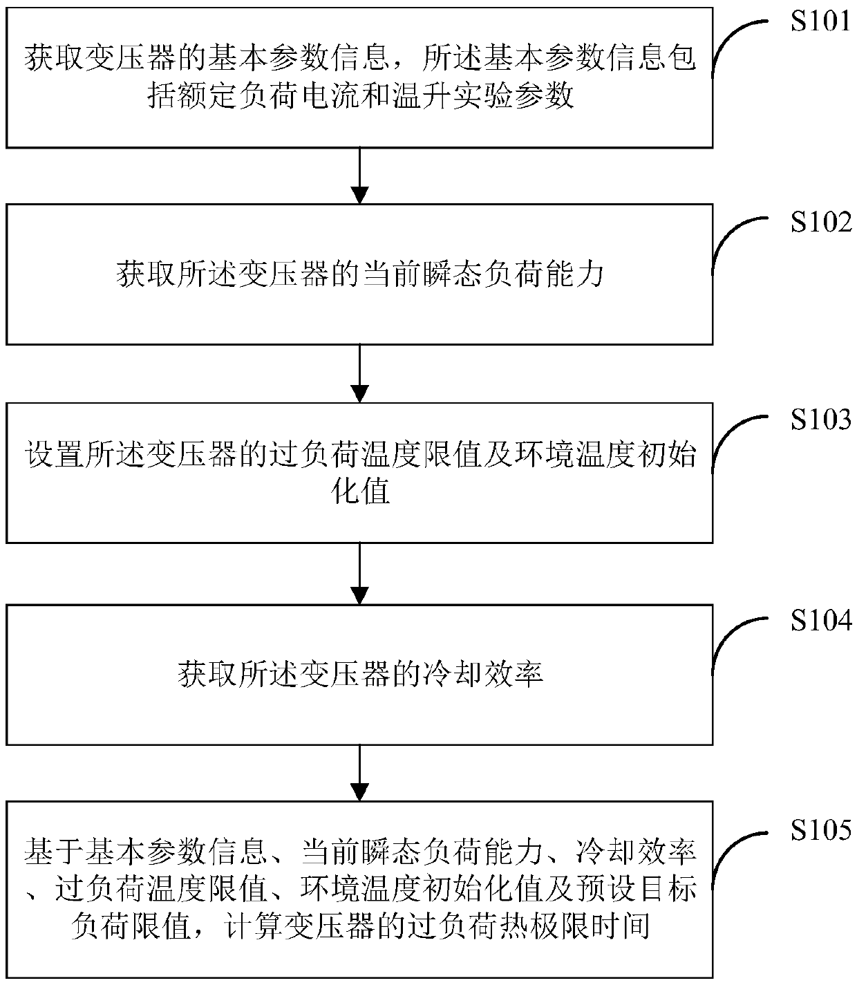
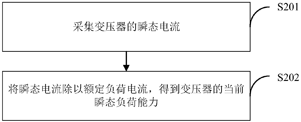
[0034] figure 1 It shows the implementation flow of a transformer overload calculation method provided by an embodiment of the present invention. The execution subject of the flow in this embodiment may be a terminal device, and the process is described in detail as follows:
[0035] In step S101, the basic parameter information of the transformer is obtained, and the basic parameter information includes rated load current and temperature rise experimental parameters.
[0036] In this embodiment, firstly, the basic parameter information of the transformer needs to be obtained, the basic parameter information includes the rated load current and the temperature rise experimental parameters, and the temperature rise experimental parameters include the top layer oil temperature limit and the hot spot temperature limit.
[0037] In this embodiment, the basic parameter information further includes transformer structural parameters, and the transformer structural parameters are used ...
Embodiment 2
[0110] Such as Figure 5 As shown, an embodiment of the present invention provides a transformer overload calculation system 1000 for performing figure 1 The method step in the corresponding embodiment, it comprises:
[0111] The basic parameter information acquisition module 1010 is used to acquire the basic parameter information of the transformer, and the basic parameter information includes rated load current and temperature rise experimental parameters;
[0112] The current transient load capacity acquisition module 1020, configured to acquire the current transient load capacity of the transformer;
[0113] The temperature setting module 1030 is used to set the overload temperature limit value and the ambient temperature initialization value of the transformer;
[0114] A cooling efficiency acquisition module 1040, configured to acquire the cooling efficiency of the transformer;
[0115] An overload thermal limit time calculation module 1050, configured to calculate ba...
Embodiment 3
[0147]The embodiment of the present invention also provides a terminal device 9, including a memory 91, a processor 90, and a computer program 92 stored in the memory 91 and operable on the processor 90, and the processor 90 executes the computer program 92 When realizing the steps in each embodiment as described in embodiment 1, for example figure 1 Step S101 to step S105 are shown. Alternatively, when the processor 90 executes the computer program 92, it realizes the functions of each module in each device embodiment as described in Embodiment 2, for example Figure 5 The functions of modules 1010 to 1050 are shown.
[0148] The terminal device may be computing devices such as desktop computers, notebooks, palmtop computers, and cloud servers. The terminal device may include, but not limited to, a processor 90 and a memory 91 . For example, the terminal device may also include an input and output device, a network access device, a bus, and the like.
[0149] The processo...
PUM
 Abstract
Description
Claims
Application Information
 - R&D
- Intellectual Property
- Life Sciences
- Materials
- Tech Scout
- Unparalleled Data Quality
- Higher Quality Content
- 60% Fewer Hallucinations
Browse by: Latest US Patents, China's latest patents, Technical Efficacy Thesaurus, Application Domain, Technology Topic, Popular Technical Reports.
© 2025 PatSnap. All rights reserved.Legal|Privacy policy|Modern Slavery Act Transparency Statement|Sitemap|About US| Contact US: help@patsnap.com


