OPC verification method for gate region

A verification method and area technology, applied in the photoengraving process of the pattern surface, the original for opto-mechanical processing, optics, etc., can solve the problems of OPC verification efficiency, no inspection-free area in the gate area, and false alarms.

Active Publication Date: 2018-10-19
SHANGHAI HUALI MICROELECTRONICS CORP
View PDF7 Cites 3 Cited by
  • Summary
  • Abstract
  • Description
  • Claims
  • Application Information

AI Technical Summary

Problems solved by technology

[0007] The purpose of the present invention is to provide an OPC verification method for the grid area, so as to solve the problem of false reporting caused by many rounded ...

Method used


Image

  • OPC verification method for gate region
  • OPC verification method for gate region
  • OPC verification method for gate region

Examples


Embodiment Construction

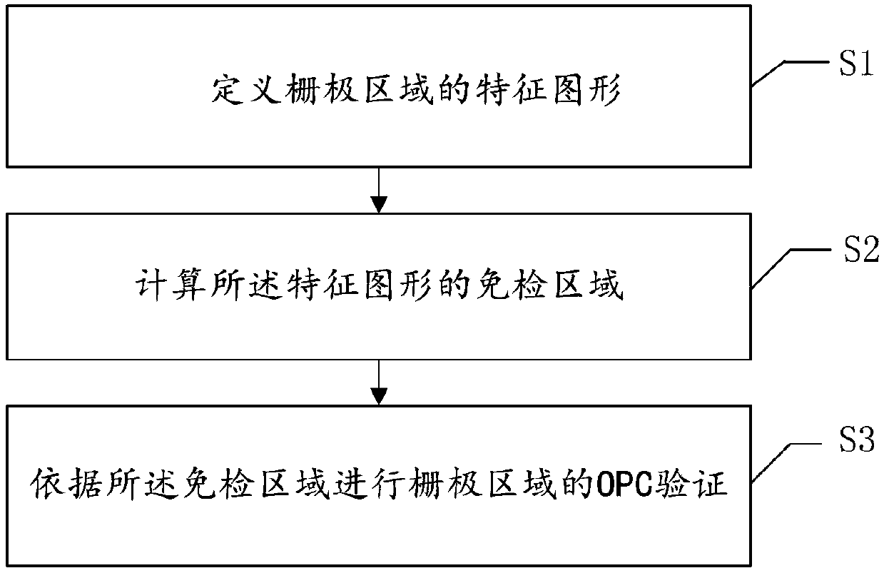
[0029] The specific implementation manner of the present invention will be described in more detail below with reference to schematic diagrams. The advantages and features of the present invention will be more apparent from the following description. It should be noted that all the drawings are in a very simplified form and use imprecise scales, and are only used to facilitate and clearly assist the purpose of illustrating the embodiments of the present invention.

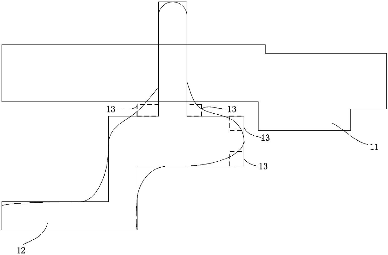
[0030] As mentioned in the background technology, when the optical proximity correction (OPC) method is used to correct the pattern on the mask, due to the existence of rounded corners in the pattern, the existing OPC verification inspection will set an exemption for this phenomenon. region to reduce false positives. Such as figure 1 As shown, in the OPC model, an inspection-free region 13 is provided on the polysilicon layer 12 above the active region layer 11 . However, when inspecting the gate area in the pol...


PUM


Abstract

The invention provides an OPC verification method for a gate region. The method comprises the following steps of defining a feature graph of the gate region; calculating an inspection-free region of the feature graph; performing OPC verification of the gate region according to the inspection-free region. According to the method provided by the invention, the inspection-free area for the gate region is specifically set in the gate region of a polysilicon layer, specifically, the inspection-free region of the gate region is set by setting the inspection-free region of the feature graph of the gate region, and the method has the advantage that the number of report errors of the gate region caused by the fillet phenomenon can be greatly reduced, thereby improving the OPC verification efficiency of the gate region.

Description

technical field [0001] The invention relates to the field of semiconductor manufacturing, in particular to an OPC verification method for a gate region. Background technique [0002] OPC (Optical Proximity Correction, Optical Proximity Correction) technology has been widely used in the publishing process of semiconductor manufacturing mask plates. At present, the most widely used OPC method is the OPC correction method based on the model. The potential imaging error of the lithography process is obtained through the simulation calculation of the OPC model, so that the target graphics are pre-corrected to compensate for the graphics distortion or deformation caused by the optical proximity effect. [0003] With the advancement of technology nodes, the feature size of semiconductor manufacturing continues to shrink, and the precision requirements for lithography imaging are getting higher and higher, which requires that the correction accuracy of OPC must meet the requirements...

Claims


Application Information

Patent Timeline
IPC IPC(8): G03F1/36
CPCG03F1/36
Inventor 齐雪蕊江志兴
Owner SHANGHAI HUALI MICROELECTRONICS CORP
Why Eureka
Try Eureka