Ground wire clamp

A grounding wire and fixture technology, applied in electrical connection sockets, wire-wound connectors, etc., can solve the problems of low efficiency, too many insulating rods, sore and weak hands and upper limbs, etc., and achieve the effect of reducing labor intensity and improving efficiency.

Active Publication Date: 2018-10-19
GUANGDONG POWER GRID CO LTD +1
View PDF4 Cites 4 Cited by
  • Summary
  • Abstract
  • Description
  • Claims
  • Application Information

AI Technical Summary

Problems solved by technology

[0002] During the installation (or removal) of the grounding wire, the action of rotating the insulating rod is repeated too much, especially when multiple sets of grounding wires are installed at one time, it is easy to cause weakness in the hands and upper limbs, resulting in reduced efficiency

Method used


Image

  • Ground wire clamp
  • Ground wire clamp
  • Ground wire clamp

Examples


Embodiment

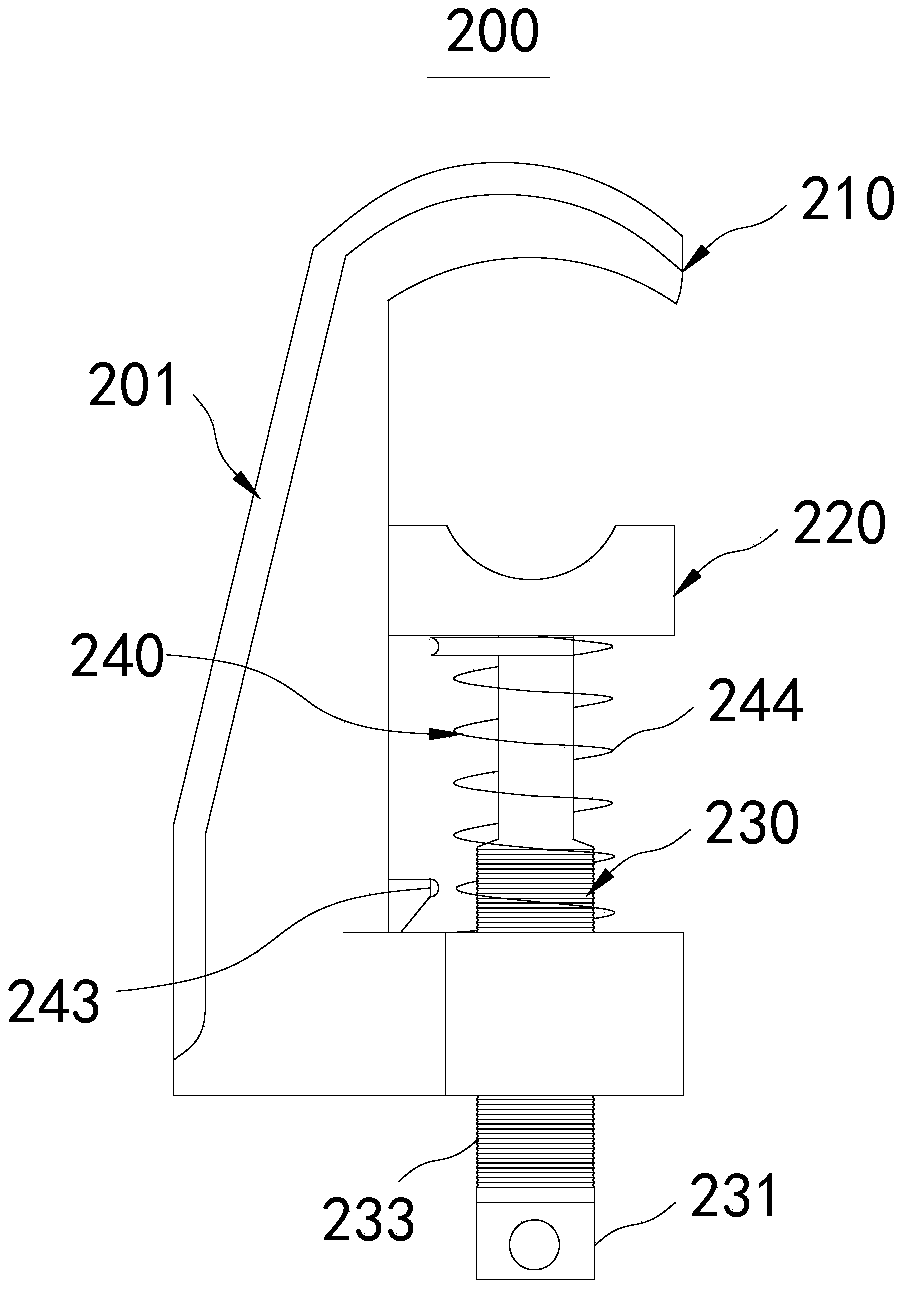
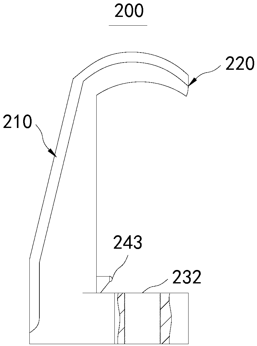
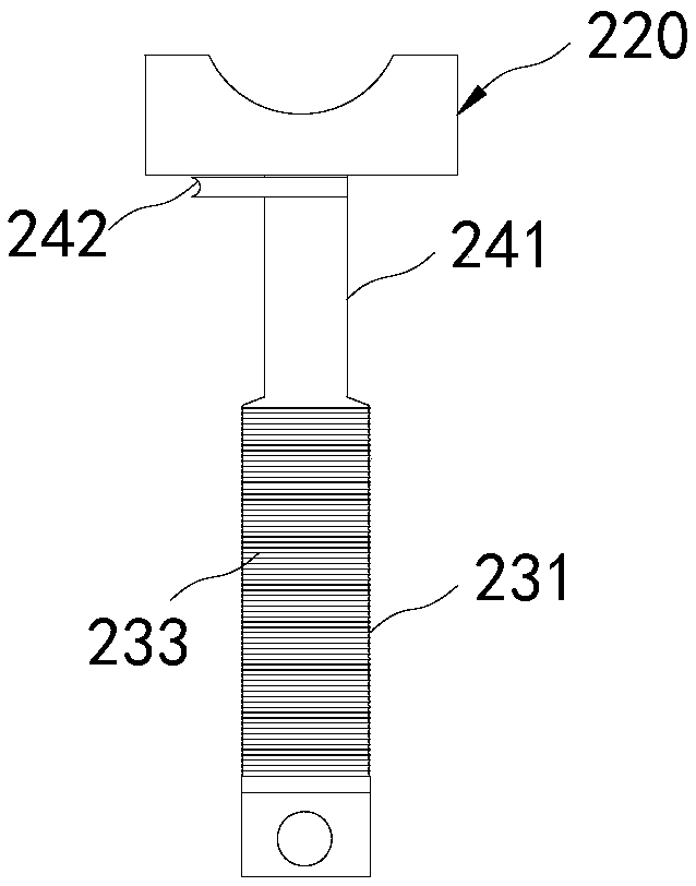
[0048] Please refer to Figure 1-Figure 3 , Figure 1-Figure 3 The specific structure of the ground wire clamp 200 provided in the embodiment is shown.

[0049] from Figure 1-Figure 3 It can be seen from the figure that the ground wire clamp 200 includes a body 201 , a first clamp 210 and a second clamp 220 .

[0050] The first clip 210 is disposed on the body 201 , and the second clip 220 is movably connected with the body 201 through the movable structure 230 .

[0051] The movable structure 230 includes a screw rod 231 and a through hole 232 arranged on the body 201; the through hole 232 is arranged on the end of the body 201 away from the first chuck 210, and an internal thread is arranged in the through hole 232, and the screw rod 231 is provided with a The external thread segment 233 that matches the internal thread, the screw rod 231 is connected with the second chuck 220 after passing through the through hole 232 .

[0052] The ground wire clamp 200 also includes ...


PUM


Abstract

The present invention relates to the field of power equipment and in particular to a ground wire clamp. The ground wire clamp includes a body, a first clamping head and a second clamping head. The first clamping head is disposed on the body. The second clamping head is movably connected to the body through a movable structure. The movable structure includes a screw rod and a through hole disposedon the body. The through hole is disposed at an end of the body away from the first clamping head. Internal threads are disposed in the through hole. The screw rod is provided with an external threadsegment fitting the internal threads. The screw rod is connected to the second clamping head after passing through the through hole. The ground wire clamp further includes an engaging structure whichincludes a transition section, a bayonet lock, and an engaging seat engaged with the bayonet lock. The engaging seat is disposed on the body and adjacent to the through hole. The bayonet lock and thetransition section are disposed on the screw rod. The transition section is located between the joint of the screw rod and the second clamping head and the external thread section. The ground wire clamp can effectively reduce the labor intensity of a worker and improve the efficiency of installing or uninstalling the ground wire clamp.

Description

technical field [0001] The invention relates to the field of electric equipment, in particular to a ground wire clamp. Background technique [0002] During the installation (or removal) of the grounding wire, the action of rotating the insulating rod is repeated too much, especially when multiple sets of grounding wires are installed at one time, it is easy to cause weakness in the hands and upper limbs, resulting in reduced efficiency. Contents of the invention [0003] The object of the present invention is to provide a grounding wire clamp, which can effectively reduce the labor intensity of workers and improve the efficiency of installing or removing the grounding wire clamp. [0004] Embodiments of the present invention are achieved like this: [0005] A ground wire clamp, including a body, a first clamp and a second clamp; [0006] The first chuck is arranged on the body, and the second chuck is movably connected with the body through a movable structure; [0007]...

Claims


Application Information

Patent Timeline
Patent Type & Authority Applications(China)
IPC IPC(8): H01R11/15H01R11/22
CPCH01R11/15H01R11/22Y02E10/50
Inventor 王永宏方祎张嘉跃刘瀚林陈传话
Owner GUANGDONG POWER GRID CO LTD
Why Eureka
Try Eureka