Quick washing pond for processing before production of dehydrated vegetables

A technology for dehydrated vegetables and cleaning pools, which is applied in the field of quick cleaning pools for pre-processing dehydrated vegetables, can solve the problems of poor cleaning effect, treatment affecting vegetable cleaning, etc., to achieve better cleaning effect and improve cleaning effect.

Active Publication Date: 2018-10-23
李奇奇
View PDF4 Cites 5 Cited by
  • Summary
  • Abstract
  • Description
  • Claims
  • Application Information

AI Technical Summary

Problems solved by technology

[0007] The purpose of the present invention is to address the shortcomings of the prior art, by setting a surge mechanism in the water tank to make the water surge up and down, and setting a horizontal push mechanism and a flow guide mechanism to cooperate to concentrate the dirt produced by cleaning in one place to overcome the problem. The cleaning effect is not good during the vegetable cleaning process, and the stolen goods generated by cleaning are difficult to deal with in time in the water, which affects the subsequent vegetable cleaning.

Method used


Image

  • Quick washing pond for processing before production of dehydrated vegetables
  • Quick washing pond for processing before production of dehydrated vegetables
  • Quick washing pond for processing before production of dehydrated vegetables

Examples


Embodiment 1

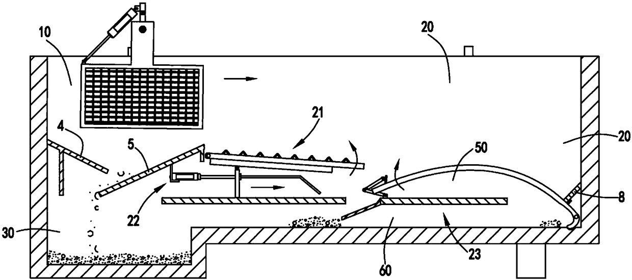
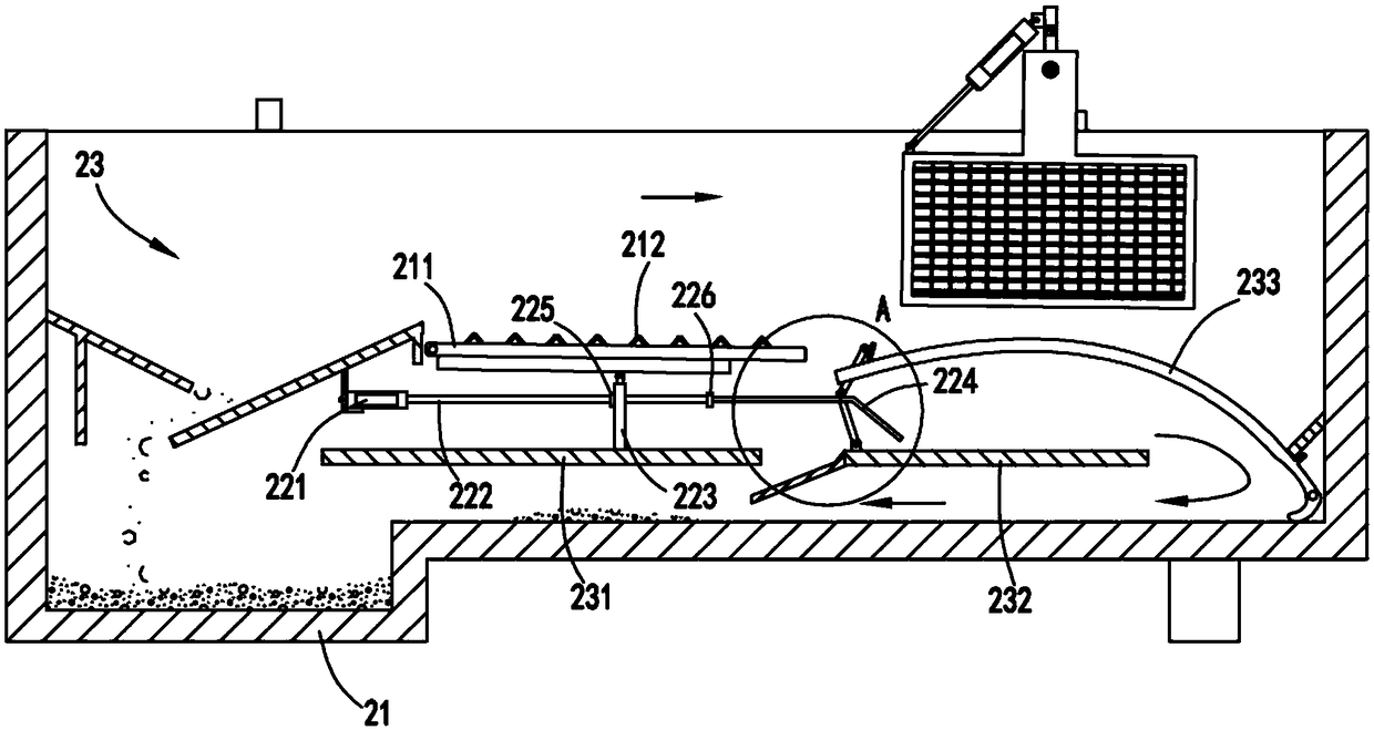
[0036] Such as figure 1 , figure 2 , image 3 , Figure 4 , Figure 5 , Figure 6 , Figure 7 As shown, a quick cleaning tank for pretreatment of dehydrated vegetables includes a water tank 1, and is characterized in that: the water tank 1 is divided into a primary cleaning area 10 and a secondary cleaning area 20 on the left and right, and the bottom of the primary cleaning area 10 is also A sludge accumulation area 30 is provided;

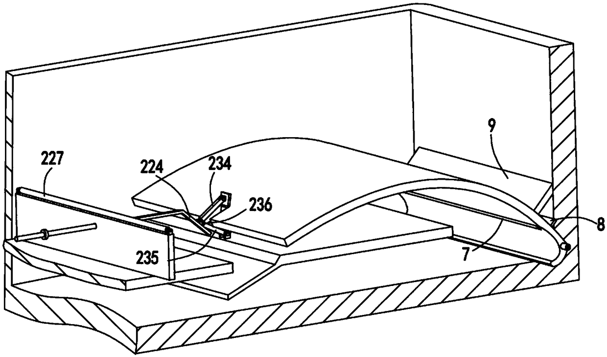
[0037] The water tank 1 is provided with a sludge cleaning device 2, and the sludge cleaning device 2 includes a surge mechanism 21 arranged below the primary cleaning area 10 for making the water surge upwards, and a surge mechanism 21 arranged below the surge mechanism 21 The horizontal pushing mechanism 22 used to push the water below the primary cleaning area 10 and the secondary cleaning area 20 to flow in the horizontal direction and cooperate with the horizontal pushing mechanism 22 to guide the flowing water flow so that it generat...

Embodiment 2

[0050] Such as figure 1 , figure 2 , image 3 , Figure 4 , Figure 5 , Figure 6 , Figure 7 As shown, the components that are the same as or corresponding to those in the first embodiment are marked with the corresponding reference numerals in the first embodiment. For the sake of simplicity, only the differences from the first embodiment will be described below. The difference between the second embodiment and the first embodiment is that the transfer mechanism 32 includes a sliding seat a321 and a sliding seat b322 respectively sliding along the front and rear upper edges of the water tank 1, and the front and rear upper edges of the water tank 1 are respectively provided with limited The position block a11 and the limit block b12, the sliding seat a321 and the sliding seat b322 both include a bracket 3211 and at least two sliding rollers 3212 rotatably arranged on the bracket 3211 .

[0051] Further, the swing mechanism 31 includes a rotating shaft 311 whose two en...


PUM


Abstract

The invention relates to a quick washing pond for processing before production of dehydrated vegetables. The quick washing pond comprises a water tank, wherein the water tank is divided into a primarywashing region and a secondary washing region from left to right; a sludge accumulation region is arranged under the primary washing region; a sludge cleaning device is arranged in the water tank, and comprises a surging mechanism, a flat pushing mechanism and a water current guiding mechanism, wherein the surging mechanism is arranged under the primary washing region, and is used for enabling water to surge upwards; the flat pushing mechanism is arranged under the surging mechanism, and is used for pushing water to flow in the horizontal direction; the water current guiding mechanism cooperates with the flat pushing mechanism to guide the flowing water currents, so that a reflux is generated by the flowing water currents to drive sludge at the bottom to the sludge accumulation region; asupporting and transferring device is also arranged in the water tank, and comprises a swing mechanism and a transferring mechanism, wherein the swing mechanism is used for supporting vegetables to bewashed and driving the vegetables to swing in water for washing; and the transferring mechanism is used for transferring the vegetables in the primary washing region to the secondary washing region.According to the quick washing pond disclosed by the invention, the problem that in the washing course of the vegetables, the washing effect is poor, and the problem that dirt generated by washing isdifficult to treat in water in time, and subsequent vegetable washing is influenced are solved.

Description

technical field [0001] The invention relates to the technical field of vegetable cleaning equipment, in particular to a quick cleaning pool for pre-production treatment of dehydrated vegetables. Background technique [0002] Before the vegetables are dehydrated, they need to be cleaned to ensure that the vegetables are dehydrated and packaged in a relatively clean state. The existing vegetable cleaning equipment has poor cleaning effect, and it is difficult to clean the sundries inside the vegetables. [0003] A Chinese invention patent with the application publication number CN107822172A discloses a vegetable cleaning device, which includes: a first housing, which is horizontally provided with a first screen and a first partition from top to bottom inside, and a first The screen can rotate relative to the first shell, the upper surface of the first partition is provided with a horizontal push rod, an annular groove, a plurality of first through holes, a horizontal cover and...

Claims


Application Information

Patent Timeline
Patent Type & Authority Applications(China)
IPC IPC(8): A23N12/02
CPCA23N12/02
Inventor 包文波杜文杰
Owner 李奇奇
Why Eureka
Try Eureka