
Liquid discharge apparatus

A technology of liquid and ejection parts, which is applied in printing devices, transportation and packaging, thin material processing, etc., and can solve problems such as image quality degradation and ink spraying position deviation

Active Publication Date: 2018-10-23
SEIKO EPSON CORP
View PDF9 Cites 0 Cited by
  • Summary
  • Abstract
  • Description
  • Claims
  • Application Information

AI Technical Summary

Problems solved by technology

[0005] However, in the inkjet printer of Patent Document 1, there are cases where a plurality of depressions are formed also at the position facing the recording head (discharging portion), and the concave parts corresponding to the depressions may be damaged. When the ink is ejected on the medium, and the deformation of the medium due to the unevenness causes the ink landing position to shift, resulting in a decrease in image quality.

Method used


Image

  • Liquid discharge apparatus
  • Liquid discharge apparatus
  • Liquid discharge apparatus

Examples


Embodiment 1

[0042] Example 1 ( Figure 1 to Figure 12 )

[0043] First, an outline of a printing device according to Embodiment 1 of the present invention will be described.

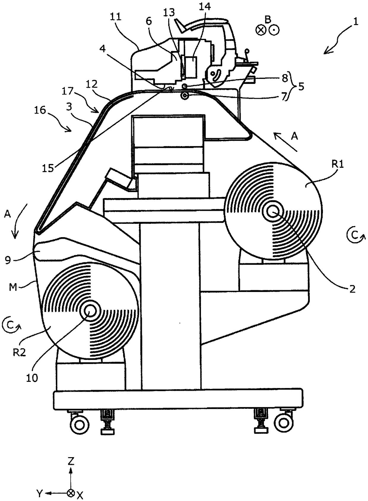
[0044] figure 1 It is a schematic side view of the printing apparatus 1 according to this embodiment.

[0045] The printing apparatus 1 of the present embodiment includes a support shaft 2 that supports a roll R1 of a roll-shaped medium M for printing. Furthermore, when the printing apparatus 1 of this embodiment transports the medium M in the transport direction A, the support shaft 2 rotates in the rotation direction C. As shown in FIG. In addition, although the roll-shaped medium M wound up with the printing surface on the outside is used in this embodiment, in the case of the roll-shaped medium M wound up on the inside with the printing surface Next, the support shaft 2 can also be rotated in a direction opposite to the rotation direction C to feed out the roll R1.

[0046]In addition, although a roll-shape...

Embodiment 2

[0088] (Example 2)( Figure 13 )

[0089] Hereinafter, Example 2, which is a configuration example in which the first support surface 3 a does not adjoin the concave-convex portion 24 of the second support surface 3 b in the conveyance direction A, will be described.

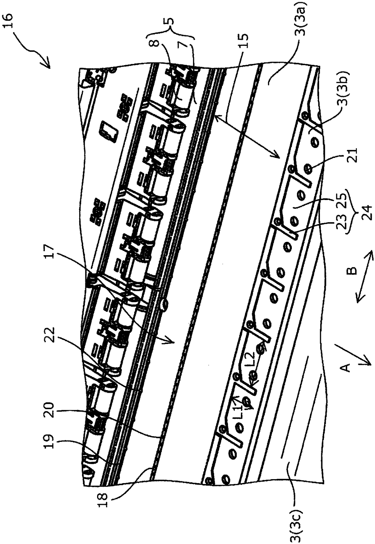
[0090] Figure 13 It is a perspective view around the ejection range 15 of the support part 17 which is the main part of the printing apparatus 1 of this embodiment, and shows the state where the medium M is not set on the conveyance path 16, and is the same as that of the first embodiment. figure 2 corresponding figure. In addition, the components common to those of the first embodiment described above are denoted by the same reference numerals, and detailed description thereof will be omitted.

[0091] In addition, in the printing device 1 of the present embodiment, the structures other than the support surface 3 are the same as those of the printing device 1 of the first embodiment.


PUM


Abstract

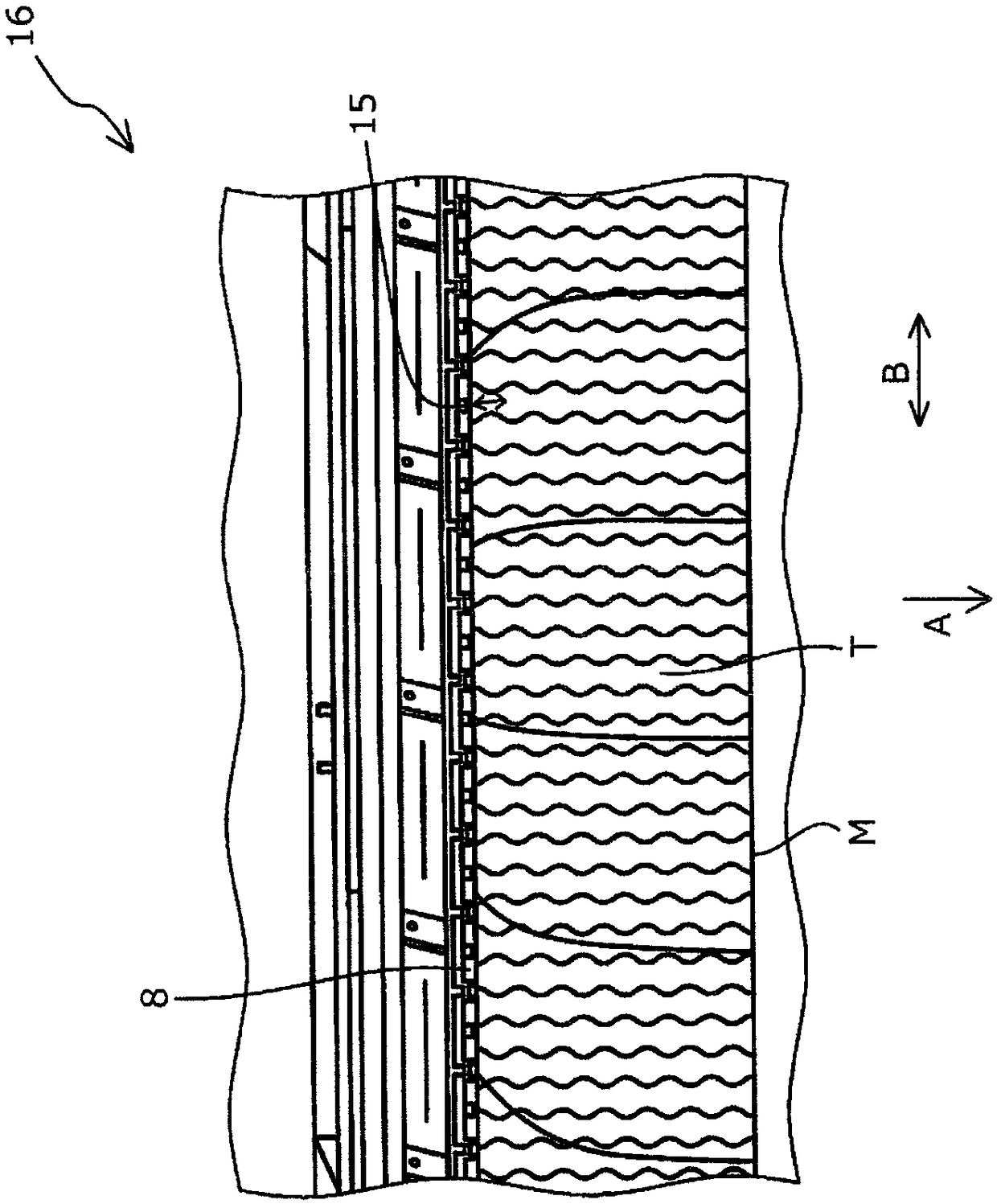
There is provided a liquid discharge apparatus (1), which can inhibit the reduction of image quality due to transported medium wrapping from a supporting surface and medium deformation. The liquid discharge apparatus (1) includes: a transporting unit (5) that transports a medium (M) in a transporting direction (A), a discharge portion (4) that discharges a liquid to the medium (M) positioned in adischarge range (15), and a supporting portion (17) that has a first supporting surface (3a) and a second supporting surface (3b), as a supporting surface (3) supporting the medium (M) to be transported by the transporting unit (5), in which the first supporting surface (3a) supports the medium (M) in the discharge range (15) and does not have unevenness in a width direction (B) intersecting the transporting direction, the second supporting surface (3b) supports the medium (M) on a downstream side of the discharge range (15) in the transporting direction and includes uneven portions in which afirst portion (23) and an uneven portion (24) of a second portion (25), which is further recessed than the first portion, are formed alternately in the width direction.

Description

technical field [0001] The present invention relates to a liquid ejection device. Background technique [0002] Heretofore, various liquid ejection devices have been used. Among them, there is a liquid ejection device that supports a conveyed medium on a support surface of a support portion, and ejects a liquid onto the medium supported on the support surface to form an image. [0003] For example, Patent Document 1 discloses an inkjet printer (liquid ejection device) that supports recording paper as a medium on a recording medium conveyance surface (support surface) and The recording paper on the recording medium conveying surface ejects ink as a liquid. [0004] In a conventional liquid ejection device in which a conveyed medium is supported on a support surface, the medium sometimes lifts up from the support surface and comes into contact with the liquid ejection portion. Therefore, Patent Document 1 describes a technique in which depressions are provided on the record...

Claims


Application Information

Patent Timeline
IPC IPC(8): B41J11/00B41J2/01
CPCB41J2/01B41J11/0085B41J11/06B65H23/28B65H2404/5211B65H2801/06B65H18/145B41J13/106B41J13/0009B41J13/14
Inventor 竹中亮太北岸幹朗
Owner SEIKO EPSON CORP
Learn More