Integrated yarn nozzle base

An integrated technology of yarn feeder seat, applied in textiles and papermaking, weft knitting, knitting, etc., can solve the problems of yarn feeder seat stuck, yarn feeder seat damage, difficult to control accurately, etc., to achieve consistent clamping force, Ease of maintenance and replacement

Pending Publication Date: 2018-10-23
QUANZHOU YONGQI PLASTIC ELECTRON
View PDF9 Cites 1 Cited by
  • Summary
  • Abstract
  • Description
  • Claims
  • Application Information

AI Technical Summary

Problems solved by technology

The clamping force and clearance between the yarn feeder seat and the sky bar can be adjusted through two waist-shaped grooves on the yarn feeder seat body, but it is difficult to control accurately, especially the gap between the yarn feeder seat and the sky bar
If the gap is too large, the yarn feeder seat will easily shake; if the gap is small, the yarn feeder seat will be easily stuck
The clamping force between the yarn feeder seat and the pole also has the problem of poor control, especially when the connecting screw between the inclined guide block assembly and the yarn feeder body is not locked, the inclined guide block becomes loose and detached from the pole , which will cause serious damage to the yarn feeder seat during operation, and if the damaged parts fall on the machine, it will cause damage to other parts of the machine
At the same time, it is inevitable that the clamping force of each yarn carrier cannot be consistent
This adjustment method has high requirements on the skill and care of the operator, and it is difficult to adjust even for skilled workers.

Method used


Image

  • Integrated yarn nozzle base
  • Integrated yarn nozzle base
  • Integrated yarn nozzle base

Examples


Embodiment 1

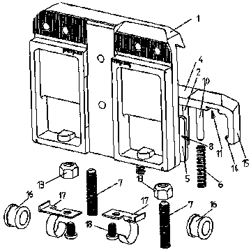
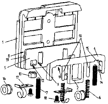
[0024] Integrated yarn carrier, such as Figure 1 to Figure 4 As shown, it includes the yarn carrier body 1, the inclined guide block assembly connected with the yarn carrier body 1, the inclined guide block assembly includes the inclined guide block body 4, the inclined guide block compression spring 6, the inclined guide block fine-tuning locking member 7 and The inclined guide block base 5 with an integrated structure with the yarn carrier body 1, there is a groove 8 for the lower part of the inclined guide block body 4 to be embedded between the yarn carrier body 1 and the inclined guide block base 5, and the inclined guide block body 4 is placed on the yarn The mouth seat body 1 can slide up and down flexibly. Due to the integrated structure of the inclined guide block base 5 and the yarn feeder body 1, the relative positions of the inclined guide block base 5 and the inclined guide block body 1 remain unchanged, so the clamping force between the yarn feeder seat and the ...

Embodiment 2

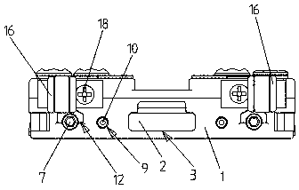
[0031] Such as Figure 5 As shown, its basic structure is the same as that of Embodiment 1, except that the perforation 12 on the base of the inclined guide block 5 is provided with an internal thread 20 that cooperates with the fine-tuning locking member 7 of the inclined guide block. In this embodiment, The fine-tuning locking part 7 of the oblique guide block adopts a screw, and the fine-tuning locking part 7 of the oblique guide block penetrates the perforation 12 and is threadedly connected with the perforation 12 to face the limit groove 11 on the oblique guide block body 4 . The fine-tuning locking part 7 of the oblique guide block and the perforation 12 are through anti-loosening treatment, and will not loosen due to vibration during the weaving process. The anti-loosening treatment can be provided with a rubber ring or coated with anti-loosening glue. There is no need to add nuts and reduce installation steps.

Embodiment 3

[0033] Such as Figure 5 As shown, its basic structure is the same as that of Embodiment 1, except that a nut insert is embedded in the through hole 12, and the inclined guide block fine-tuning locking member 7 penetrates the through hole 12 and is connected with the nut insert.


PUM


Abstract

The invention relates to yarn guiding mechanism of a computer flat knitting machine and discloses an integrated yarn nozzle base. The integrated yarn nozzle base comprises a yarn nozzle base body andan inclined guide block assembly connected to the integrated yarn nozzle base body; the inclined guide block assembly comprises an inclined guide block pressure spring, an inclined guide block fine-turning locking member, an inclined guide block base connected to the yarn nozzle base and an inclined guide block body movably connected to the inclined guide block base; a groove for the embedding ofthe lower part of the inclined guide block body is installed between the yarn nozzle base body and the inclined guide block base; the inclined guide block pressure spring is installed between the inclined guide block base and the inclined guide block body; one end of the inclined guide block pressure spring is abutted to the lower end of the inclined guide block base and the other end is abutted to the inclined guide block body; the yarn nozzle base body is provided with through holes for the passing through of the inclined guide block fine-turning locking member; the inclined guide block fine-turning locking member passes through the through hole and is threaded with the inclined guide block base. The yarn nozzle base body of the invention is provided with the inclined guide block fine-turning locking member threaded with an adjusting nut; through rotating the inclined guide block fine-turning locking member, the gap between the yarn nozzle base and a top bar.

Description

technical field [0001] The invention relates to a yarn guide mechanism of a computerized flat knitting machine, in particular to an integrated yarn feeder seat. Background technique [0002] On the flat knitting machine, the yarn feeder seat is composed of the yarn feeder body, horns and inclined guide block components. The clamping force and gap between the yarn feeder seat and the sky bar can be adjusted through two waist-shaped grooves arranged on the yarn feeder seat body, but it is difficult to control accurately, especially the gap between the yarn feeder seat and the sky bar. If the gap is large, the yarn feeder seat is prone to shaking; if the gap is small, the yarn feeder seat is prone to jamming. The clamping force between the yarn feeder seat and the pole also has the problem of poor control, especially when the connecting screw between the inclined guide block assembly and the yarn feeder body is not locked, the inclined guide block becomes loose and detached fr...

Claims


Application Information

Patent Timeline
Patent Type & Authority Applications(China)
IPC IPC(8): D04B15/56
CPCD04B15/56
Inventor 杨鹭晖杨明海吕聪雕
Owner QUANZHOU YONGQI PLASTIC ELECTRON
Why Eureka
Try Eureka