Abutting-locking type butterfly valve

A locking, butterfly valve technology, used in lift valves, valve devices, engine components, etc., can solve problems such as increased costs for enterprises

Active Publication Date: 2018-10-23
江苏磊霆精密新材料有限公司
View PDF7 Cites 3 Cited by
  • Summary
  • Abstract
  • Description
  • Claims
  • Application Information

AI Technical Summary

Problems solved by technology

[0002] Butterfly valve is a kind of regulating valve with relatively simple structure. It is usually mainly used for cutting off or throttling various types of fluids such as water in pipelines, various corrosive media, mud, oil products, and liquid metals. Various types of fluids; the existing butterfly valve generally includes a valve body, a valve plate, and a driving rod. The driving rod drives the valve plate to rotate,

Method used


Image

  • Abutting-locking type butterfly valve
  • Abutting-locking type butterfly valve
  • Abutting-locking type butterfly valve

Examples


Embodiment Construction

[0022] The content of the present invention will be further described in detail below in conjunction with the accompanying drawings.

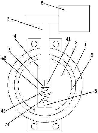
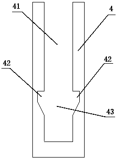
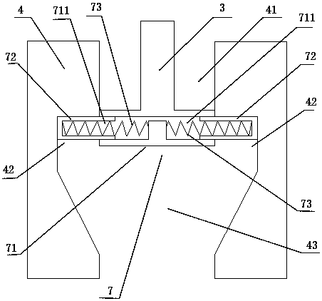
[0023] Such as Figure 1 to 7 As shown, a pressure locking butterfly valve includes a valve body 1, a valve plate 2, a connecting sleeve 4, a driving rod 3, a telescopic assembly 7, and a pressure screw 8. The valve body 2 has an annular structure; the valve plate 2 is installed inside the valve body 1; the connecting sleeve 4 is fixedly installed on one side of the valve plate 2; the upper end of the connecting sleeve 4 is open, The connecting sleeve 4 is provided with an insertion cavity 41; the lower two sides of the insertion cavity 41 each extend to the outside with a clamping groove 42; the lower end of the clamping groove 42 is provided with a tapered sliding groove 43; The tapered slide groove 43 has a tapered structure with a large upper and a small lower end; the lower end of the driving rod 3 is equipped with a telescopic assembly 7; t...


PUM


Abstract

The invention discloses an abutting-locking type butterfly valve. The abutting-locking type butterfly valve comprises a valve body, a valve plate, a connection sleeve, a drive rod, a telescopic assembly and an abutting screw rod; the bottom of the connection sleeve is provided with a threaded channel; and the abutting screw rod penetrates through the threaded channel at the bottom of the connection sleeve in a threaded mode to abut against the lower end of a positioning block. According to the abutting-locking type butterfly valve, as the abutting screw rod can penetrate through the threaded channel at the bottom of the connection sleeve in the threaded mode to abut against the lower end of the positioning block, the positioning block can be connected with the connection sleeve more firmlyin the longitudinal space, the positioning block can be positioned in the longitudinal direction, and thus a telescopic barrel and the connection sleeve can be more firmly connected in a clamped mode.

Description

Technical field [0001] The invention relates to a pressure-resistant locking butterfly valve. Background technique [0002] Butterfly valve is a relatively simple regulating valve, usually mainly used for cutting off or throttling various types of fluids such as water in pipelines, various corrosive media, mud, oil, liquid metal, etc. It is precisely because it is mainly aimed at Various types of fluids; the existing butterfly valve generally includes a valve body, a valve plate, and a drive rod. The valve plate is sealed and connected to the inside of the valve body. The drive rod passes through the valve body and is fixed on one side of the valve plate. By rotating the drive rod, The drive rod drives the valve plate to rotate, thereby completing the opening and closing process of the valve plate and the valve body; but at present, the drive rod and the valve plate are generally fixedly connected. Once the drive rod is damaged, the entire valve plate must be replaced, adding to ...

Claims


Application Information

Patent Timeline
IPC IPC(8): F16K1/22F16K1/48
Inventor 朱银德
Owner 江苏磊霆精密新材料有限公司
Why Eureka
Try Eureka