Biomass gasification burner

A burner and biomass technology, applied in combustion methods, combustion equipment, solid fuel combustion, etc., can solve the problems of low gasification rate of biomass fuel, unreasonable design of oxygen supply equipment, large smoke and dust emissions, etc.

Pending Publication Date: 2018-10-23
雷连净
View PDF1 Cites 0 Cited by
  • Summary
  • Abstract
  • Description
  • Claims
  • Application Information

AI Technical Summary

Problems solved by technology

[0002] The biomass gasification burner in the prior art has the following disadvantages: (1) Direct combustion is used, resulting in low thermal efficiency and large smoke and dust emissions, which is not conducive to environmental protection; (2) It is not equipped with oxygen supply equipment or oxygen supply equipment The design is unreasonable, the combustion is insufficient, and a large amount of tar, carbon monoxide and other substances produced cannot be decomposed, causing tar to block the pipeline, and carbon monoxide is filled in the hopper of biomass fuel, so the gasification rate of biomass fuel is low; (3) The structure is complex and the cost is high, which is not conducive to the widespread use of residents in daily life and is not conducive to promotion

Method used


Image

  • Biomass gasification burner
  • Biomass gasification burner
  • Biomass gasification burner

Examples


Embodiment 1

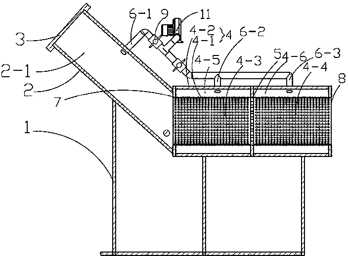
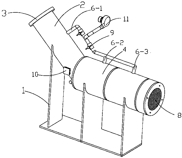
[0038] as attached figure 1 To attach figure 2 As shown, a biomass gasification burner includes a bracket 1, a primary combustion tube 2 is fixedly installed on the top of the bracket 1, the interior of the primary combustion tube 2 is a combustion chamber 2-1, and the nozzle at one end of the primary combustion tube 2 is fuel Inlet 3, the other end is connected with a secondary combustion tube 4; the secondary combustion tube 4 includes a secondary combustion inner tube 4-1 and a secondary combustion outer tube 4-2 coaxially arranged with the secondary combustion inner tube 4-1 , the cracking disc 5 arranged in the secondary combustion tube 4 divides the secondary combustion inner tube 4-1 into a gasification chamber 4-3 and a fire chamber 4-4, and the gasification chamber 4-3 and the fire chamber 4-4 They are communicated through the fire hole on the cracking disc 5; the mouth of the secondary combustion tube 4 outer end is also covered with a dust filter 8, the secondary ...

Embodiment 2

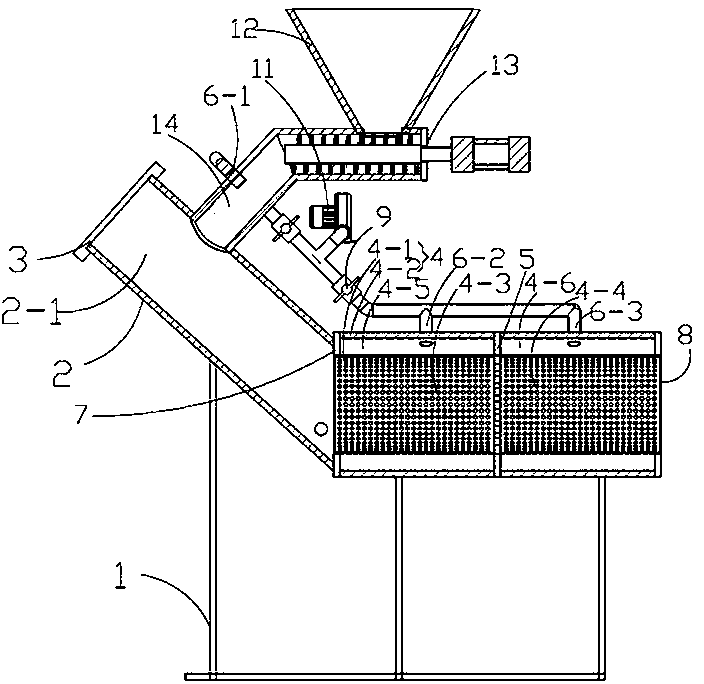
[0043] as attached image 3 To attach Figure 4 As shown, a biomass gasification burner includes a bracket 1, a primary combustion tube 2 is fixedly installed on the top of the bracket, the primary combustion tube 2 is a combustion chamber 2-1, and the nozzle at one end of the primary combustion tube 2 is a fuel inlet 3 , the other end communicates with a secondary combustion tube 4; the secondary combustion tube 4 includes a secondary combustion inner tube 4-1 and a secondary combustion outer tube 4-2 coaxially arranged with the secondary combustion inner tube 4-1, the secondary combustion tube 4 The cracking disc 5 that is set in the secondary combustion tube 4 divides the secondary combustion inner tube 4-1 into a gasification chamber and a fire chamber 4-4, and the gasification chamber and the fire chamber 4-4 pass through the cracking disc 5. The fire hole is connected; the outer end of the secondary combustion pipe 4 is also covered with a dust filter 8.

[0044] The s...

Embodiment 3

[0049] as attached Figure 5 To attach Figure 8 As shown, a biomass gasification burner includes a bracket 1, a primary combustion tube 2 is fixedly installed on the top of the bracket 1, the primary combustion tube 2 is a combustion chamber, the nozzle at one end of the primary combustion tube 2 is a fuel inlet 3, and the other One end communicates with a secondary combustion tube 4; the secondary combustion tube 4 includes a secondary combustion inner tube 4-1 and a secondary combustion outer tube 4-2 coaxially arranged with the secondary combustion inner tube 4-1. The cracking disc 5 arranged in the tube 4 divides the secondary combustion inner tube 4-1 into a gasification chamber 4-3 and a fire injection chamber 4-4, and the gasification chamber 4-3 and the fire injection chamber 4-4 are separated by cracking The fire holes on the disc 5 are connected; the outer end of the secondary combustion tube 4 is also covered with a dust filter 8 .

[0050] The secondary combusti...


PUM


Abstract

The invention provides a biomass gasification burner. The biomass gasification burner comprises a bracket, and a primary combustion tube is fixedly mounted at the top of the bracket. The nozzle at oneend of the primary combustion tube is a fuel inlet, and the other end of the primary combustion tube communicates with a secondary combustion tube. The secondary combustion tube comprises a secondarycombustion inner tube and a secondary combustion outer tube. A cracking disk arranged in the secondary combustion tube separates the secondary combustion inner tube into a gasification chamber and aflaming cavity, and the gasification chamber communicates with the flaming cavity through flame outlet holes in the cracking disk. The secondary combustion inner tube, the secondary combustion outer tube and the primary combustion tube enclose an annular cavity, and the cracking disk separates the annular cavity into a secondary oxygen supply chamber and a tertiary oxygen supply chamber. The secondary oxygen supply chamber communicates with the gasification chamber through vent holes, and the tertiary oxygen supply chamber communicates with the flaming cavity through the vent holes. A secondary oxygen supply tube and a tertiary oxygen supply tube separately communicate with the secondary oxygen supply chamber and the tertiary oxygen supply chamber. The biomass gasification burner can fullyburn biomass fuel, has high thermal efficiency and high gasification rate, and is beneficial to environmental protection.

Description

technical field [0001] The invention relates to a burner, in particular to a biomass gasification burner. Background technique [0002] The biomass gasification burner in the prior art has the following disadvantages: (1) Direct combustion is used, resulting in low thermal efficiency and large smoke and dust emissions, which is not conducive to environmental protection; (2) It is not equipped with oxygen supply equipment or oxygen supply equipment The design is unreasonable, the combustion is insufficient, and a large amount of tar, carbon monoxide and other substances produced cannot be decomposed, causing tar to block the pipeline, and carbon monoxide is filled in the hopper of biomass fuel, so the gasification rate of biomass fuel is low; (3) The structure is complex and the cost is high, which is not conducive to the widespread use of residents' daily life and is not conducive to promotion. Therefore, how to develop a biomass gasification burner with low manufacturing c...

Claims


Application Information

Patent Timeline
Patent Type & Authority Applications(China)
IPC IPC(8): F23B10/02F23L1/00F23L9/00
CPCF23B10/02F23L1/00F23L9/00
Inventor 雷连净
Owner 雷连净
Why Eureka
Try Eureka