A Scanning Polarization LiDAR System for Atmospheric Particulate Matter Monitoring

An atmospheric particulate matter, scanning polarization technology, applied in the optical field, can solve the problems of being susceptible to electromagnetic interference, clumsy radar, reducing the service life of the radar main body, etc. performance effect

Active Publication Date: 2021-07-13
吉林省洪科光电技术有限公司
View PDF0 Cites 0 Cited by
  • Summary
  • Abstract
  • Description
  • Claims
  • Application Information

AI Technical Summary

Problems solved by technology

[0002] The traditional optical system has the problem that the transmitting unit and the receiving unit are not in the same axis, and the optical stability is greatly affected by temperature due to different structural parts, and the receiving signal is greatly affected by the background sunlight, which makes signal analysis difficult.
[0003] The traditional emission light source mostly adopts the external optical fiber type, which has problems such as unstable emission signal and short life; the traditional signal processing system has low extraction accuracy for weak signals and is susceptible to electromagnetic interference; the traditional atmospheric aerosol lidar Scanning uses the rotation of the radar body, which is very clumsy and the radar is exposed to the outside for a long time, which reduces the service life of the radar body and is greatly affected by the weather.
[0004] Part of the new atmospheric aerosol lidar uses a split scanning device, but it cannot solve the problem of synchronization between the recording system and the scanning system, and cannot achieve arbitrary angle locking and 360° continuous rotation
[0005] The traditional forensics system cannot realize long-distance high-definition day and night forensics, without optical fog penetration, laser lighting and other functions; the traditional software system has no independent database, etc.

Method used


Image

  • A Scanning Polarization LiDAR System for Atmospheric Particulate Matter Monitoring
  • A Scanning Polarization LiDAR System for Atmospheric Particulate Matter Monitoring
  • A Scanning Polarization LiDAR System for Atmospheric Particulate Matter Monitoring

Examples


Embodiment Construction

[0021] In order to make the purpose, technical solution and advantages of the present invention more clear, the present invention will be further described in detail below in conjunction with the accompanying drawings and embodiments. It should be understood that the specific embodiments described here are only used to explain the present invention, not to limit the present invention.

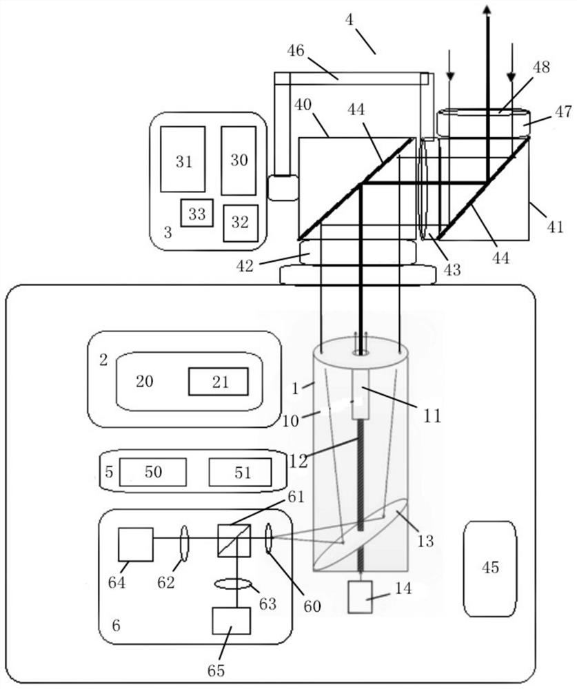
[0022] refer to Figure 1 to Figure 7 , an atmospheric particle monitoring scanning polarization laser radar system, including a transceiver system 1, a display system 2, a evidence collection system 3, a scanning system 4, a signal processing system 5, and an optical signal processing system 6; the transceiver system 1, display system 2, Both the signal processing system 3 and the optical signal processing system 6 are located in the housing. The scanning system 4 includes a horizontal rotation box 40, a vertical rotation box 41 and a linkage rod 46. The horizontal rotation box 40 is connected...


PUM


Abstract

The invention relates to a scanning polarization lidar system for monitoring atmospheric particles, including a transceiver system, a display system, a evidence collection system, a scanning system, a signal processing system, and an optical signal processing system; the transceiver system, display system, signal processing system, and optical signal The processing systems are all located in the casing, the scanning system includes a horizontal rotation box, a vertical rotation box and a linkage rod. The horizontal rotation box is coaxially arranged with the transceiver system, and the optical signal processing system matches the position of the transceiver system. The invention can effectively reduce the optical path offset caused by structural strain, has high overall monitoring performance and monitoring accuracy, is less affected by the weather, and can realize long-distance monitoring and rotary scanning in both horizontal and vertical directions. Atmospheric aerosol lidars sold in the market cannot rotate 360° horizontally without limit and synchronize forensics.

Description

technical field [0001] The invention relates to the field of optics, in particular to a scanning polarization laser radar system for monitoring atmospheric particles. Background technique [0002] The traditional optical system has the problem that the transmitting unit and the receiving unit are not in the same axis, and the optical stability is greatly affected by temperature due to different structural parts, and the receiving signal is greatly affected by the background sunlight, which makes signal analysis difficult. [0003] The traditional emission light source mostly adopts the external optical fiber type, which has problems such as unstable emission signal and short life; the traditional signal processing system has low extraction accuracy for weak signals and is susceptible to electromagnetic interference; the traditional atmospheric aerosol lidar Scanning uses the rotation of the radar body, which is very clumsy and the radar is exposed to the outside for a long t...

Claims


Application Information

Patent Timeline
Patent Type & Authority Patents(China)
IPC IPC(8): G01N15/06
CPCG01N15/06G01N2015/0693
Inventor 杨洪武
Owner 吉林省洪科光电技术有限公司
Why Eureka
Try Eureka