
Rotating bracket for machine tool

A technology for rotating bearings and machine tools, which is applied to metal processing mechanical parts, large fixed members, metal processing equipment, etc., can solve the problems of cumbersome installation, complex structure, inconvenient disassembly and assembly, and achieve flexible rotation, noise reduction, and convenient disassembly. the effect of

Inactive Publication Date: 2016-07-27
周银峰
View PDF0 Cites 0 Cited by
  • Summary
  • Abstract
  • Description
  • Claims
  • Application Information

AI Technical Summary

Problems solved by technology

Most of the rotating devices in machine tool accessories in the prior art have complex structures, many accessories, cumbersome installation, high cost and inconvenient disassembly

Method used


Image

  • Rotating bracket for machine tool

Examples


Embodiment Construction

[0009] The present invention will be further described below in conjunction with the drawings.

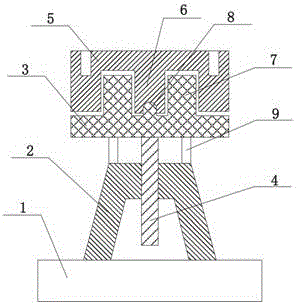
[0010] See figure 1 The rotary support for a machine tool of the present invention includes a base 1, and also includes an elastic pad 2, a mounting plate 3, and a rotating plate 5. The elastic pad 2 has a hollow trapezoidal structure, and the bottom of the elastic pad 2 is fixed On the base 1, a screw hole is provided on the top, a screw 4 is provided in the screw thread, the mounting plate 3 is provided on the top surface of the screw 4, and the middle of the upper surface of the mounting plate 3 is provided with a rotating protrusion 8, and the mounting plate 3 has a rotating protrusion. A positioning block 7 is arranged around the upper part 8, a rotating shaft 6 is arranged on the lower surface of the rotating plate 5, and a groove matching the rotating protrusion 8 is arranged on the bottom of the rotating shaft 6, and the rotating plate 5 is connected to the mounting plate thro...


PUM


Abstract

The invention discloses a rotating bracket for a machine tool. The rotating bracket comprises a base, and further comprises an elastic cushion block, a mounting plate and a rotating plate; the elastic cushion block is totally a hollow trapezoidal structure; the bottom of the elastic cushion block is fixed on the base, and a screw hole is formed in the top; a screw rod is arranged in a thread; the mounting plate is arranged on the top surface of the screw rod; a rotating projection is arranged at the middle part of the upper surface of the mounting plate; positioning blocks are arranged around the rotating projection on the mounting plate; a rotating shaft is arranged on the lower surface of the rotating plate; a groove matched with the rotating projection is formed in the bottom of the rotating shaft; the rotating plate is rotationally connected with the rotating projection of the mounting plate through the rotating shaft; and a mounting hole is formed in the upper surface of the rotating plate. The rotating bracket is novel and reasonable in structural design, has performances of reducing the vibration and lowering the noise, can adjust the height, and is flexible in rotation, low in cost and convenient for disassembly and assembly.

Description

Technical field [0001] The invention relates to a support, in particular to a rotary support for machine tools. Background technique [0002] With the development of the automation industry of my country's machine tool industry, the structural upgrade and technological progress of the machine tool industry have achieved greater development, which has also accelerated the transformation of my country's new industrialization road relying on technological progress and sustainable development. However, the machine tool manufacturing industry is an important manifestation of my country's high-end equipment manufacturing industry. With the machine tool industry’s increasing requirements for product production precision and efficiency, my country’s machine tool industry currently urgently needs to adopt a large number of ordinary machine tool accessories, machine tool accessories and machine tool numerical control. The transformation fits. Most of the rotating devices in the machine too...

Claims


Application Information

Patent Timeline
IPC IPC(8): B23Q1/01
CPCB23Q1/01B23Q1/015
Inventor 周银峰
Owner 周银峰
Learn More